Flight
3D Printed Nylon Composite Quadrocopter Frame
In order to achieve a unique and customizable quadrocopter frame I decided it would be most affordable to design the frame using Autodesk Inventor and then print the frame through the services offered by Shapeways. The frame is constructed by a process know as selective laser sintering in which a 3D printer bonds together 0.1mm layers of nylon powder with a laser. This process yields highly accurate and detailed models and costs approximate $1.50 per cubic centimeter of material from Shapeways. The nylon material, more specifically know as polyamide 2200, is somewhat flexible and very light weight with a density of 0.93 grams per cubic centimeter, lighter than carbon fiber. PA2200 has a fairly high tensile strength of 48MPa, higher than most plastics including ABS plastic; and it is capable of elongating by 24% before failing. Due to its flexible properties, it should be well suited for absorbing some of the motor vibrations and it should also hold together well in minor crashes and hard landings. Although it is not nearly as strong a carbon fiber or G10 fiberglass, it is one of the strongest and lightest materials available for 3D printing.
Revision 1:
Below is the first revision of the quadrocopter frame. It incorporates an octagonal frame with landing skids mounted to the bottom of the frame and a simple roll bar across the top. The volume of plastic necessary to print this model is approximately 22 cubic centimeters.
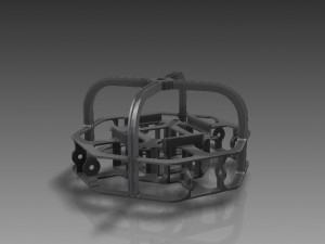
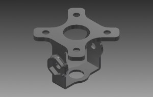
After receiving the completed plastic parts, I noticed several design flaws. The web like design of the frame had many areas of excess plastic which weren’t equally distributing the load on the frame. Since the frame was opened at the center and there were no supporting beams to distribute the load of the arms across the center, the frame was more flexible than anticipated.
Revision 2:
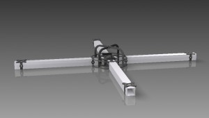
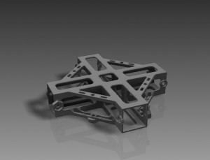
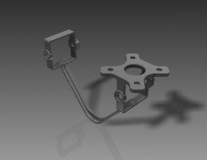
Below is the second revision of the quadrocopter frame. In order to address the structural defects of the first revision the frame was redesigned from the ground up. This revision uses square tubes which run along the entire length of each inserted arm, adding much rigidity and equally distributing the applied load. The walls to hold the control board seen in the first revision were removed so that any quadcopter board with 45mm hole spacing could be mounted atop the frame. Additionally, rails were added between each arm for not only structural support but increased range of mounting possibilities for the receiver or any other electronic sensors or accessories. Each rail is designed with a hole for mounting the controller board with bolts as well as two slots for anchoring electronics to the frame using zip-ties. Instead of attaching conventional helicopter like landing gear to the base of the central frame, springy legs were attached to each of the motor mounts in order to prevent tipping of the quadrocopter upon takeoff and landing. The volume of plastic necessary to print this model is approximately 21 cubic centimeters.

Stress Analysis:
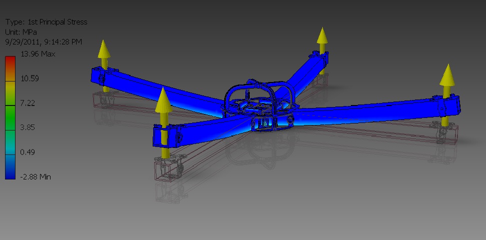
This stress analysis simulates the effects all four rotors pulling up on the frame at maximum throttle (10N), assuming that the frame is grounded.
Revision 1:

Revision 2:

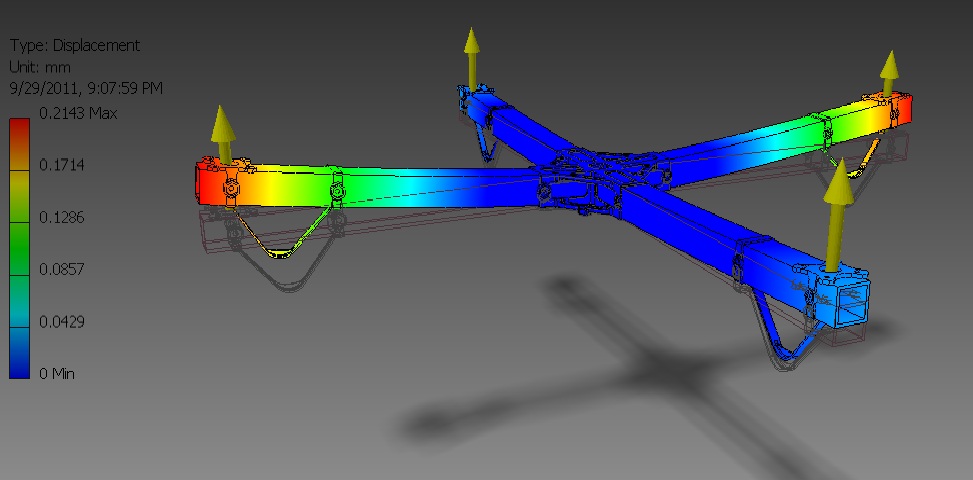
Average displacement of revision two is 46% of the displacement from the first revision making the second revision more than twice as rigid. The first principle stress shows that the first frame focuses massive amounts of pressure on several small points at the center of the frame. This pressure builds to 14MPa at each of the corners in the center of the frame between each arm. In contrast, the second frame more evenly distributes the stress and focuses a maximum load of 7Mpa at any point on the frame. Ultimately, this means that the strength of the second frame revision is approximately twice that of the first revision. While the first frame would fail with a load or impact of approximately 50N on each arm, the second frame should be able to withstand forces upwards of 100N on each arm. This is a significant increase in the load bearing efficiency of the second design.
UPDATE: 10/10/11
After finally recieving all of my parts from hobbyking I was able to complete the assembly of my quadrocopter. Unfortunately, the first revision of the frame needed improvements which I added to revision 2, however, the printing of a second frame put me over budget so I decided to assemble the frame from some lighter weight balsa arms and sheet metal. Pictures of the completed quadrocopter are linked below, hopefully I will have some video up in the future and maybe some fpv.
