Electronics
Capacitor Charger Revisited
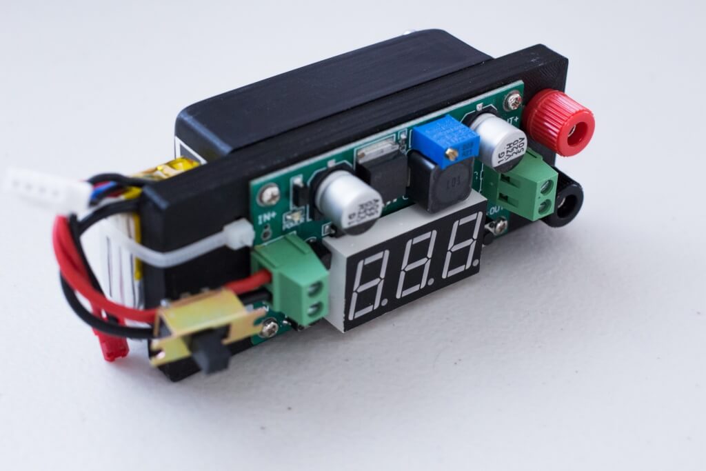
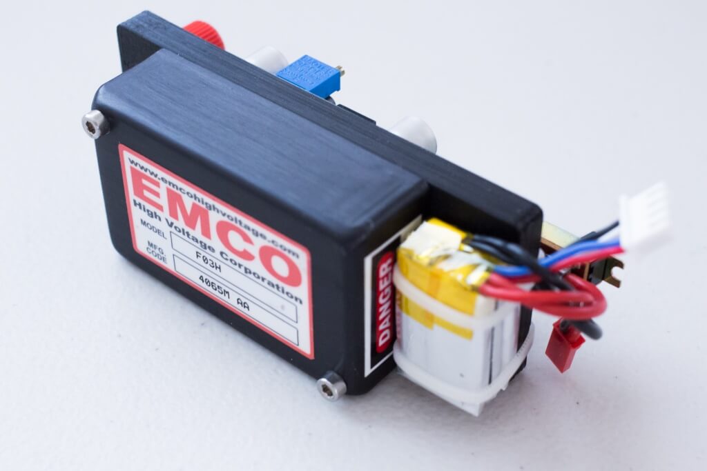
Over the past few years I have revisited my coilgun and capacitor charging projects several times. My first attempt at designing a LT3751 flyback capacitor charger was never functional, possibly due to poor soldering and a bad PCB layout. My second attempt lacked technical ambition and simply involved slapping an ebay LM2596 adjustable voltage step-down regulator on a high-voltage EMCO F03H DC-DC converter. This solution is very low noise and works reliably every time, but charges slowly at about 33mA and has a terrible form factor. I use it as a baseline when testing or as my backup.
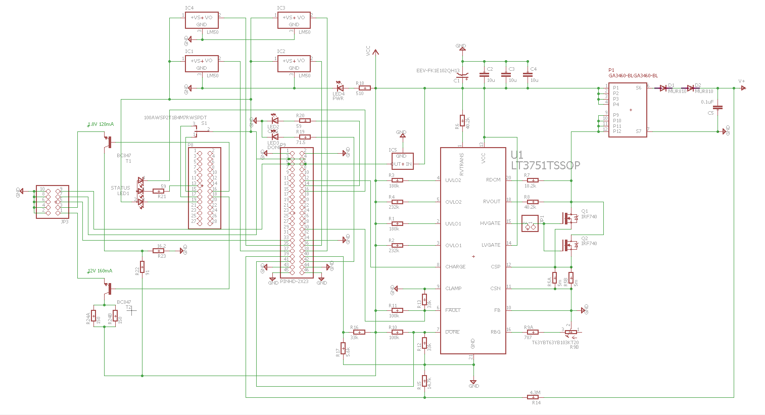
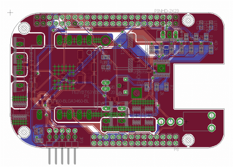
Mostly recently, I decided to once again try to integrate a LT3751 charge circuit onto a custom BeagleBone Black shield. This was certainly the most complicated way to approach the task, but very much fully featured. The shield has multiple sensors providing temperature feedback for the flyback transformer, FETs, rectifier and the LT3751. It also has analog voltage inputs for voltage sensing, programmable LED indicators, etc. After spending an exorbitant amount of time designing the board, I realized it was a bad idea to continue with something this complex before designing a simple prototype.
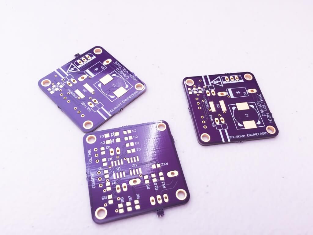
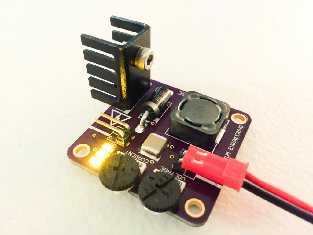
I then chose to prototype a very simple high-voltage boost converter using a 555 timer driving a STP13N65M2 NFET with a series inductor, rectifier and voltage divider with a comparator to reset the timer at full charge. The drive frequency is adjustable, effectively providing a means to adjust the charging current, and the voltage cutoff is also adjustable. I tested a variety of inductors to optimize the size, charge time and heat dissipation. It came down to using either the 390uH Coilcraft MSS1278 or RFS1317. The RFS1317 had the lowest resistance, and therefore was capable of the fastest charge time (1800uF to over 300V in 6 seconds at 15kHz). Whereas the MSS1278 was very compact, but took longer to charge (11 seconds at 4kHz, 34 seconds at 15kHz). For the RFS1317, any frequency below 15kHz generated far too much heat with no reduction in charge time. Similarly with any frequency below 4kHz for the MSS1278. I chose to use the MSS1278, which I then replaced with the Bourns SRR1260. I designed the timing circuit accordingly to allow for an adjustable frequency range that would accommodate 4-15kHz. The components easily fit on a 1.5″ square board.
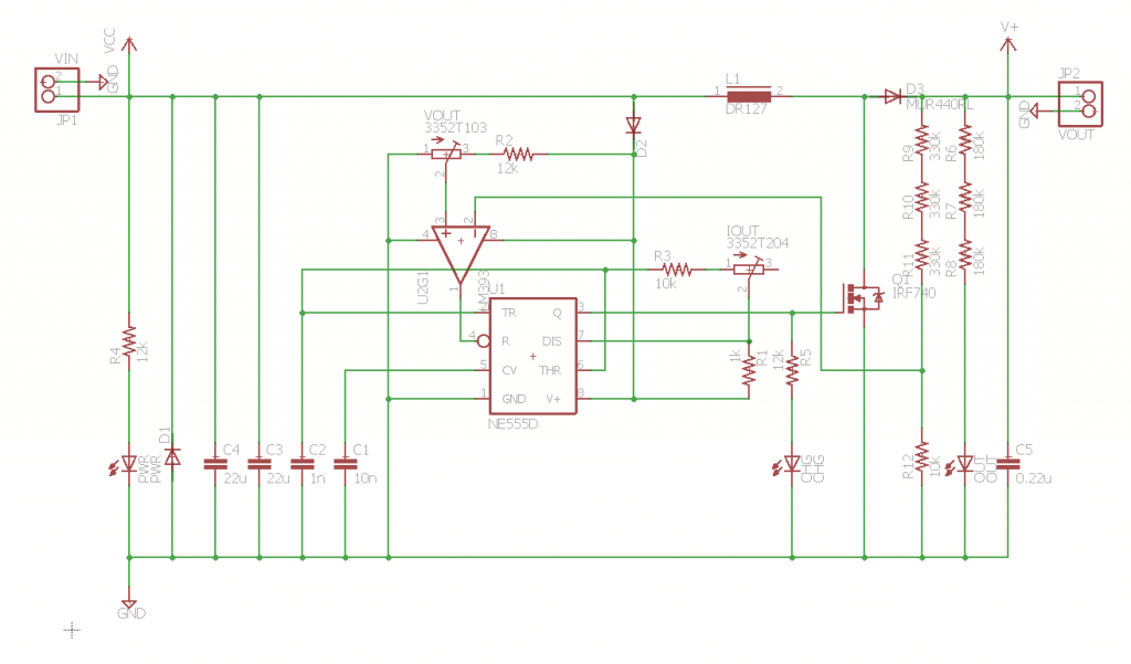

Despite numerous tests of a fully functional prototype on my breadboard, the final implementation had some problems. The timer appeared to either be resetting or operating at the wrong frequency. My guess is that there is parasitic capacitance between the components. This seems to be supported by the fact that as I apply pressure with my finger to the board I would notice an audible change in frequency. Sometimes it would work fine, other times it would do nothing. A second board behaved the same way to varying degrees. From measurement of the output, it is obvious that this design is extremely noisy. For the intended application, noise is not an issue, but for a clean high-voltage power supply, it certainly would be. A solution to this problem requires further investigation, and perhaps a better component layout or timer configuration. Having carefully designed every aspect of this project from the ground up, it has been quite a learning experience and an improvement over my last attempted charging circuit. Design files for the miniHVPSU can be found here.