Other
Custom MultiWii Motor Mixes
Although the standard MultiWii firmware offers an abundance of multirotor mixes, some less common designs remain absent. Modifying the firmware to support custom mixes is rather easy and allows for a wide range of frame options. I will first start by introducing the concept behind the motor mixes and an example mix of a quadcopter with an x orientation.
The way a motor mix works is by specifying the magnitude of the forces that should be applied to each motor. Motors that are placed farther away from the center of gravity will require a greater amount of thrust to travel the same distance as a motor that has been placed near to the center of gravity. Where this can become tricky is when determining the rudder magnitudes of a frame that is not symmetrical diagonally across the center of gravity. However, the easiest rule to follow is to assume that half of the rotors will spin clockwise and the other half will spin counter-clockwise with equal and opposing magnitudes.
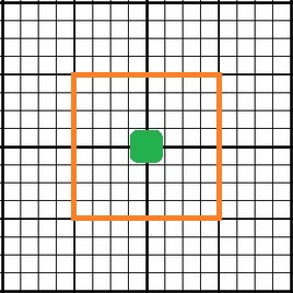
First begin with a grid that resembles the one shown below. The green box symbolizes the flight controller at the center of gravity. The origin of the grid is assumed to be at the flight controller with the orange boundary outlining a box that is 1 unit from the flight controller on each side (1/4 unit spaces).
Begin by placing the motors around the flight controller, red represents a clockwise spinning rotor and blue represents a counter-clockwise spinning rotor. Each motor should be placed roughly within the bounds of the orange box such that the x and y coordinates of each motor are about +/- 1 unit from the fight controller.
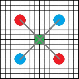
Using the grid as an aid, determine the magnitude of the pitch, roll and yaw mix by measuring the coordinates of the motor. For example, the mix for this quadx would be:
#if def QUADX
motor[0] = PIDMIX(-1,+1,-1); //REAR_R
motor[1] = PIDMIX(-1,-1,+1); //FRONT_R
motor[2] = PIDMIX(+1,+1,+1); //REAR_L
motor[3] = PIDMIX(+1,-1,-1); //FRONT_L
#endif
The syntax of the mix would be as follows:
*Be aware of the sign change!
“motor[‘motor number’] = PIDMIX( ‘- X-Coordinate’, ‘- Y-Coordinate’, ‘Rotation (‘clockwise ‘-‘, counter-clockwise’+’)’);
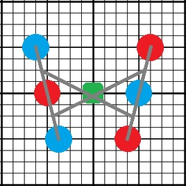
Here is an example of a custom V6 hexacopter motor mix:
#ifdef HEX6V
motor[0] = PIDMIX(+5/4,-1,+5/4); //FRONT_L
motor[1] = PIDMIX(-1 , 0,+1 ); //MID_R
motor[2] = PIDMIX(+3/4,+1,+3/4); //REAR_L
motor[3] = PIDMIX(+1 , 0,-1 ); //MID_L
motor[4] = PIDMIX(-5/4,-1,-5/4); //FRONT_R
motor[5] = PIDMIX(-3/4,+1,-3/4); //REAR_R
#endif
You may notice that the yaw magnitudes are not equal to + or – 1. This is because the frame is not symmetrical diagonally across the center of gravity. If + or – 1 was used for the rudder mix, then the aircraft would sweep very wide during turns as if the frame was rotating about a point to the rear of the aircraft where the two outer arms would intersect. For this mix, the magnitude of the rudder is equal to that of the roll magnitudes, causing the aircraft to yaw about its center.
Another point worth mentioning is the number assigned to each motor of the mix. MultiWii is capable of handling up to eight motors. These motors must each be wired to a specific pin on the flight controller and their assignments can be completely arbitrary. If the controller is labeled with pins M0-M7, then the motor number of each mix will directly correspond to these pins. However, if the board is only labeled with the digital pin numbers, then the mix must be defined accordingly:
For flight controllers assigned the “PROMINI” designation, such as boards with an ATMEGA328 or ATMEGA 168:
Motor 0 = Digital Pin 9
Motor 1 = Digital Pin 10
Motor 2 = Digital Pin 11
Motor 3 = Digital Pin 3
Motor 4 = Digital Pin 6
Motor 5 = Digital Pin 5
Motor 6 = Analog Pin A2
Motor 7 = Digital Pin 12
For flight controllers assigned the “MEGA” designation, such as boards with an ATMEGA1280 or ATMEGA2560:
Motor 0 = Digital Pin 3
Motor 1 = Digital Pin 5
Motor 2 = Digital Pin 6
Motor 3 = Digital Pin 2
Motor 4 = Digital Pin 7
Motor 5 = Digital Pin 8
Motor 6 = Digital Pin 9
Motor 7 = Digital Pin 10
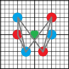
Here is one final example of a custom frame mix for a U or crescent shaped hexacopter:
#ifdef HEX6U
motor[0] = PIDMIX(+1,-1,+1); //FRONT_L
motor[1] = PIDMIX(-1 , 0,+1); //MID_R
motor[2] = PIDMIX(+1/2,+1,+1/2); //REAR_L
motor[3] = PIDMIX(+1 , 0,-1 ); //MID_L
motor[4] = PIDMIX(-1,-1,-1); //FRONT_R
motor[5] = PIDMIX(-1/2,+1,-1/2); //REAR_R
#endif
There are four modifications that must be made in order to implement the custom mix into the MultiWii code:
1) Each of the mixes written above must be added to the ‘Output‘ tab at about line 750, after the default motor mixes.
2) Add a frame definition to ‘config.h‘ such as “#define HEX6V” or “#define HEXU6”
3) Add an argument to ‘def.h‘ at about line 1000 that allows for the correct model to be displayed in the GUI. You will need to choose from a pre-existing model with the same number of motors.
#elif defined(HEX6X) || defined(HEX6V) || defined(HEX6U)
#define MULTITYPE 10
4) Add an argument to ‘def.h’ at about line 1100 that allows for the correct number of motors to be defined.
#elif defined(Y6) || defined(HEX6) || defined(HEX6X) || defined(HEX6V) || defined(HEX6U)
#define NUMBER_MOTOR 6
Now that all of the code is done, select your new frame type from config.h and upload the code to the board. With irregular shaped frames that aren’t diagonally symmetrical, it is best to reduce the yaw rates on your transmitter before testing the yaw control. Yaw may be slower or result in adverse pitch or roll manipulations if the mix is not properly configured. However, adjusting the yaw magnitudes may not necessarily correct for all of the side effects. Enabling auto-leveling will help to make most of these disappear.