Flight
Super Simple Micro H-Quad
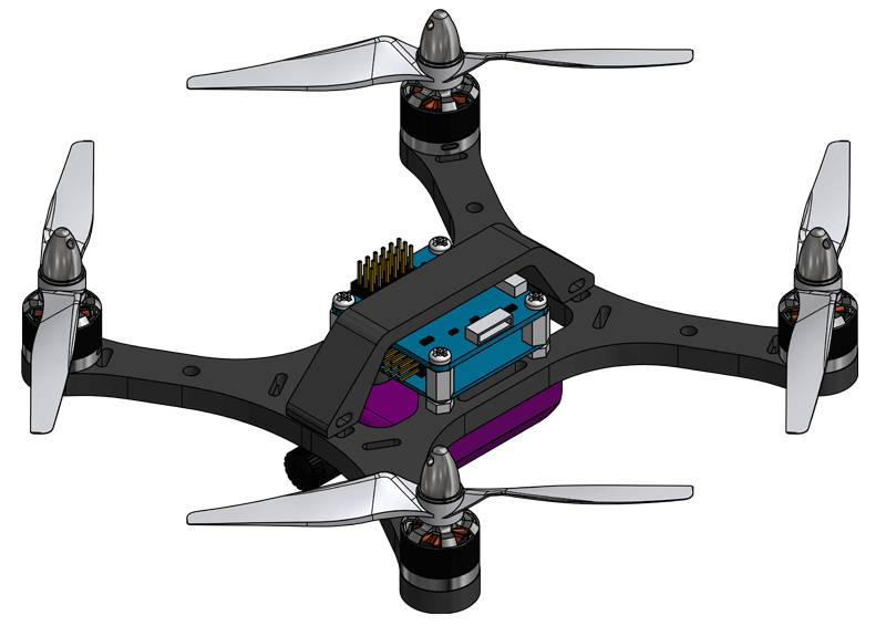
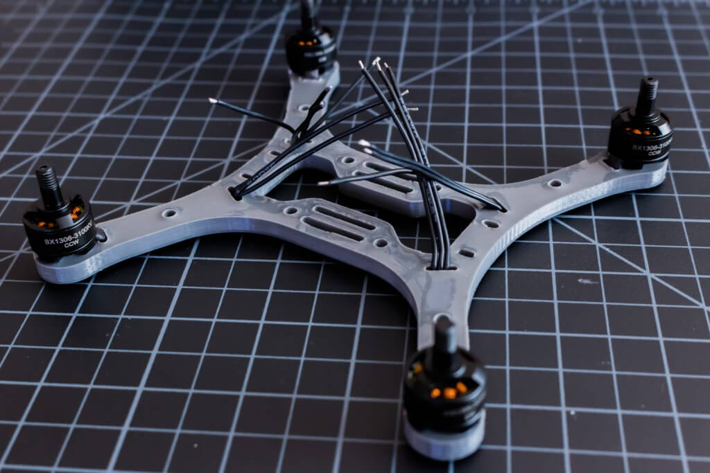
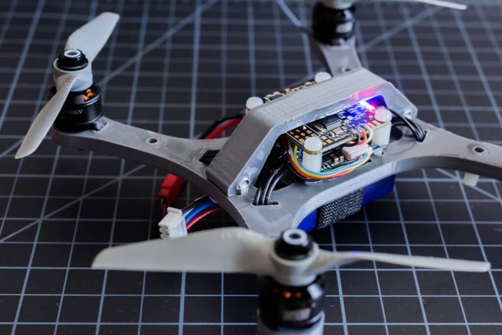
The SSHQuad Micro has all of the same simple and effective features as the larger 250mm SSHQuad PRO, but in an even smaller 170mm micro format. The SSHQuad Micro is designed to accommodate 4” props with many standard components, such as 1306 motors, 30mm flight controllers and 6/12A ESCs. Configured as recommended, a 6:1 thrust to weight ratio can be achieved with a total mass of 165 grams.
Recommended Bill of Materials:
[Qty. 1] SSHQuad 170mm Micro Frame
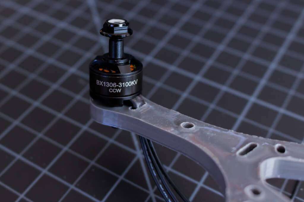
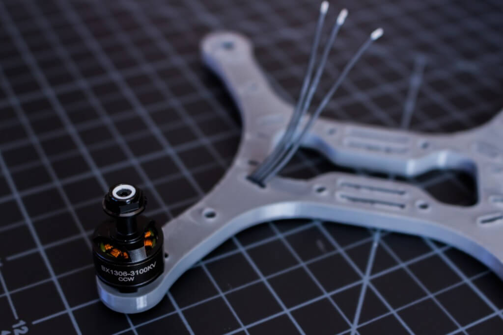
[Qty. 2] DYS BX1306-3100KV (pair)
[Qty. 1] 12A HV 4in1 ESC (w/ DuPont Cable)
[Qty. 1] Naze 32 Acro (no pins)
[Qty. 1] FrSky D4R-II
[Qty. 1] 450mAh 3S 65~130C NanoTech LiPo
[Qty. 2] APC 4141E Propeller
[Qty. 2] APC 4141EP Propeller
[Qty. 1] M5 Low-profile CW Prop Nut (4)
[Qty. 1] M5 Low-profile CCW Prop Nut (4)
[Qty. 1] M2x8mm Bolt (20)
[Qty. 1] M3 8mm Nylon Spacer (10)
[Qty. 1] M3x20mm Nylon Screw (10)
[Qty. 1] M3 Nylon Nut (10)
Assembly:
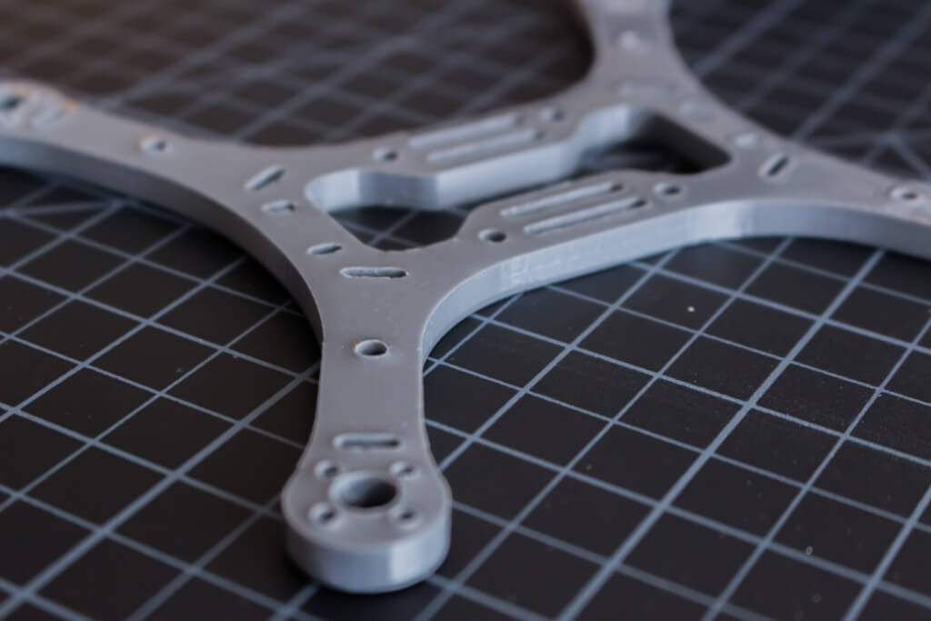
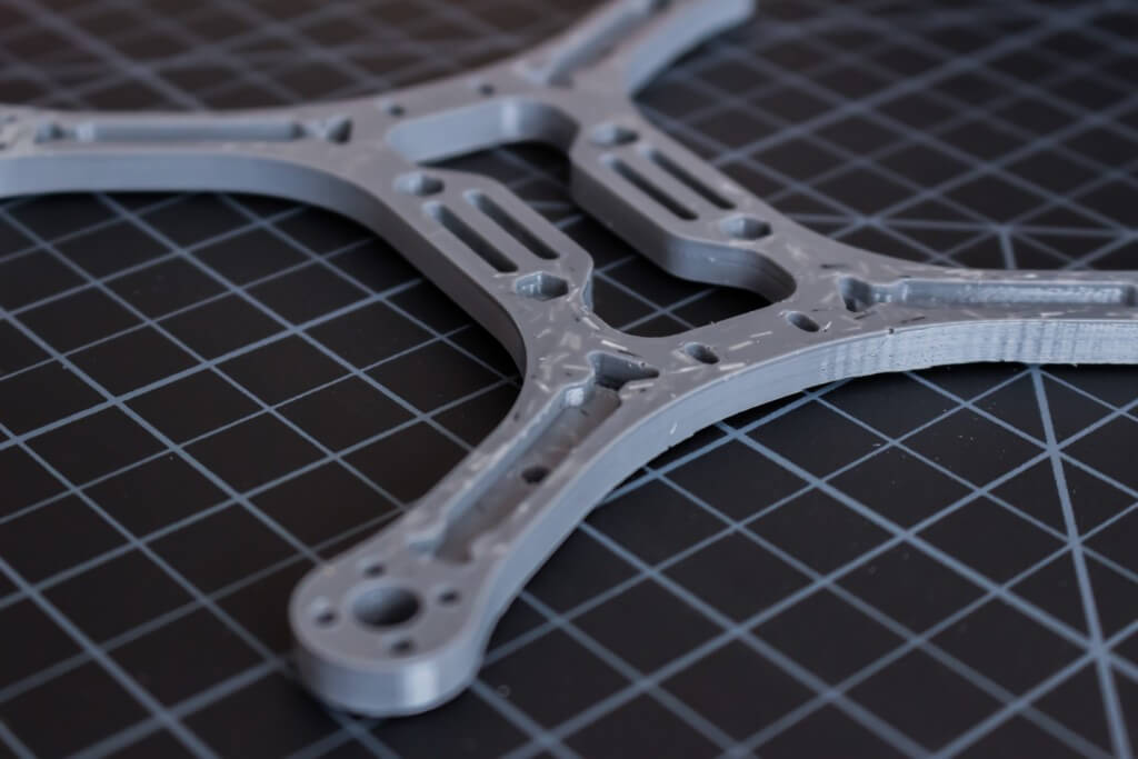
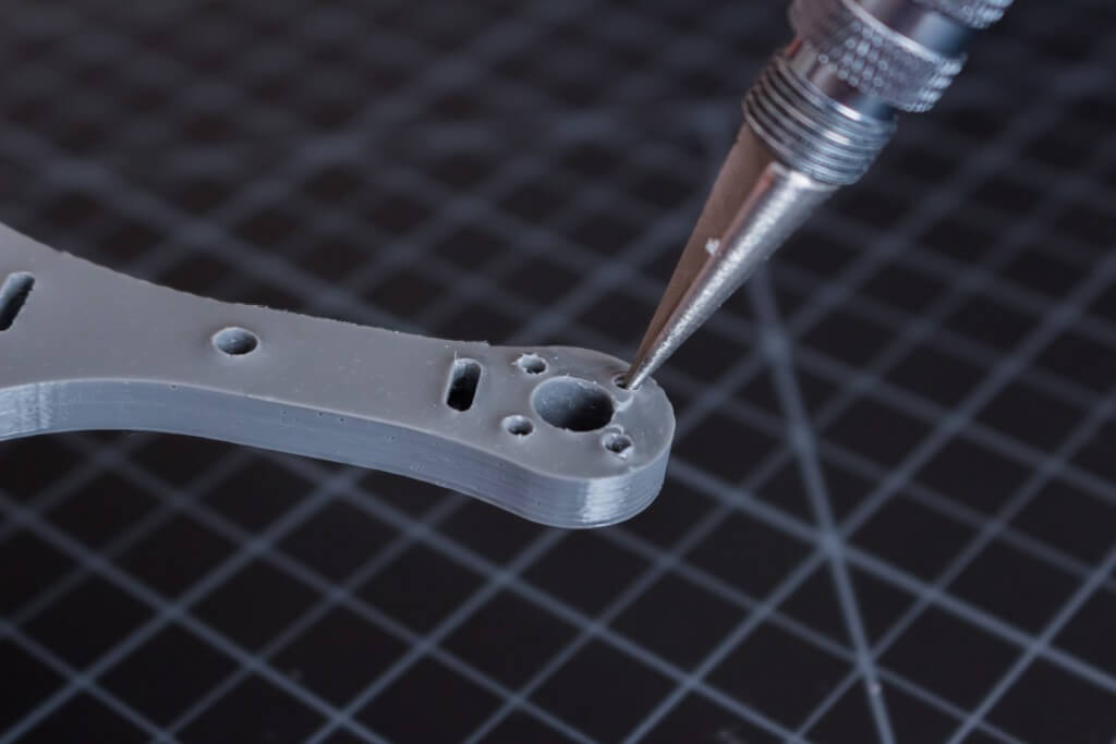
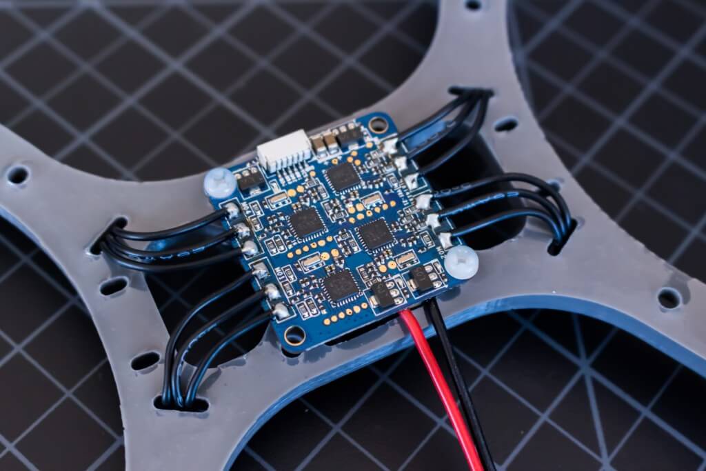
The top side of the SSHQuad Mini frame is a flat mounting surface with a high gloss finish. Beneath the frame are four channels for routing wires, mounting landing gear or embedding LEDs. Prior to assembly, a reamer or hobby knife should be used to clear out each mounting hole and ensuring a nearly flat mounting surface for the motors.
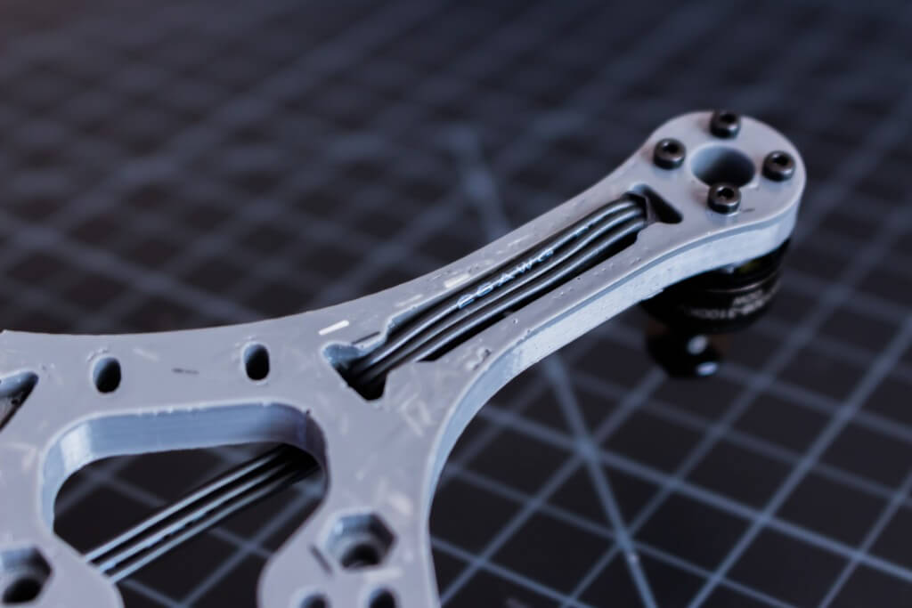
Carefully bend the motor wires near the base of the motor and insert the cables through the routing slot at the end of each arm. Using four M2x8mm bolts per motor, secure the motors to each arm and route the wires beneath the arm to the center of the frame. Each motor wire should be cut to approximately 9cm in length to reach the 4in1 ESC. Cut a strip of Velcro and route it through the battery strap slots at the center of the frame.
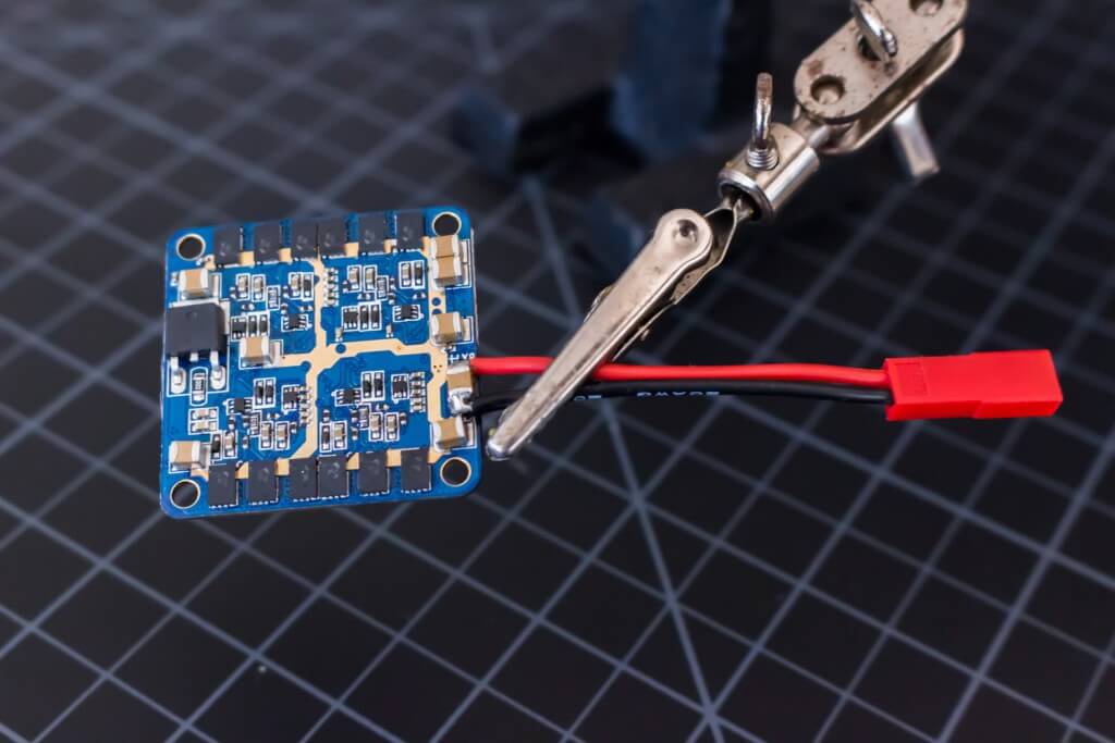
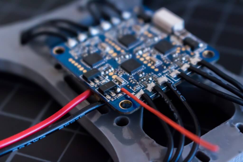
Solder a cable with battery connector to the solder pads on the bottom of the 4in1 ESC opposite the signal wires. Solder each of the motor wires to the top side of the ESC, crossing the appropriate wires to ensure proper rotation of the motor. If the ESC will later be reprogrammed for reverse operation, the order of the wire connections does not matter. Ensure that ESC outputs label M03 and M02 are located at the front of the frame with the main power on the right side and signals wires to the left when viewed from above. Bolts or standoffs may be used to temporarily secure the ESC while soldering for proper alignment.
The 4in1 ESC must now be reprogrammed with BLHeli firmware if so desired. Connect the 4in1 ESC to a battery for power and the ground and M01 signal wire to a programmer, such as the Turnigy USB Linker. Leave the red 5V BESC wire disconnected from the programmer. Open the BLHeliSuite programming tool and select the Turnigy USB Linker as the programming device. Set the BAUD rate to 9600 and connect to the ESC. Flash the latest version of BLUESERIES 12A MULTI to the ESC. Once complete, reverse the rotation direction of the motor if necessary. Alter the following settings and repeat the process for each ESC by disconnecting the previous signal wire and connecting the next signal wire to the programmer.
4in1 ESC:
M03 M02
M04 M01
M01: standard rotation
M02: reverse rotation
M03: standard rotation
M04: reverse rotation
PWM Frequency/Damped: DAMPED LIGHT (Enable ONESHOT using Cleanflight Configurator)
Motor Timing: HIGH
Temp Protection: ON
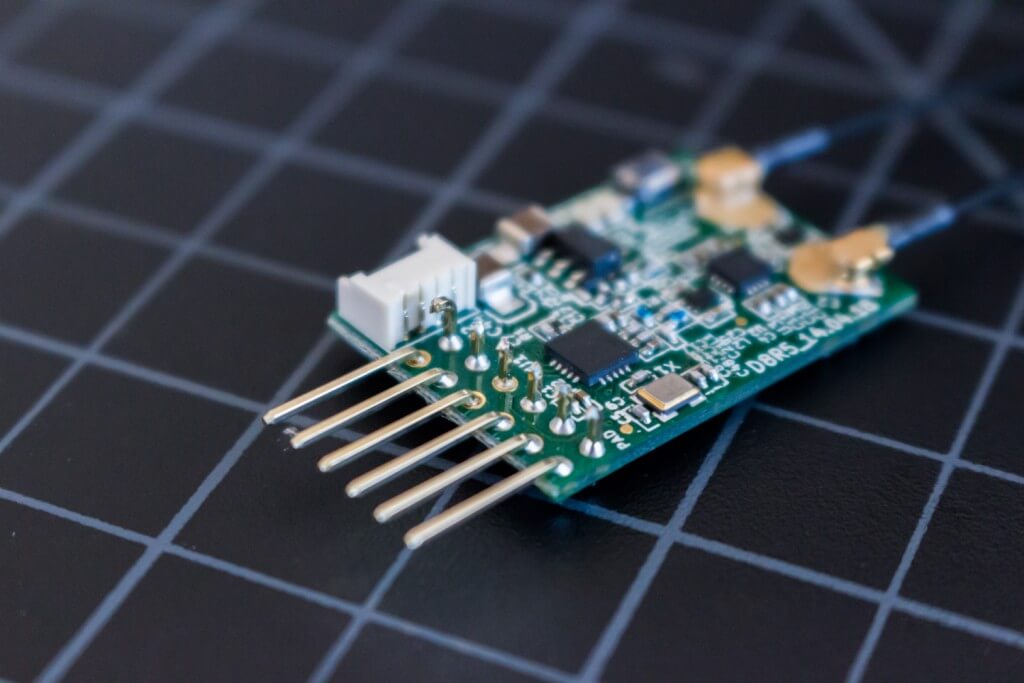
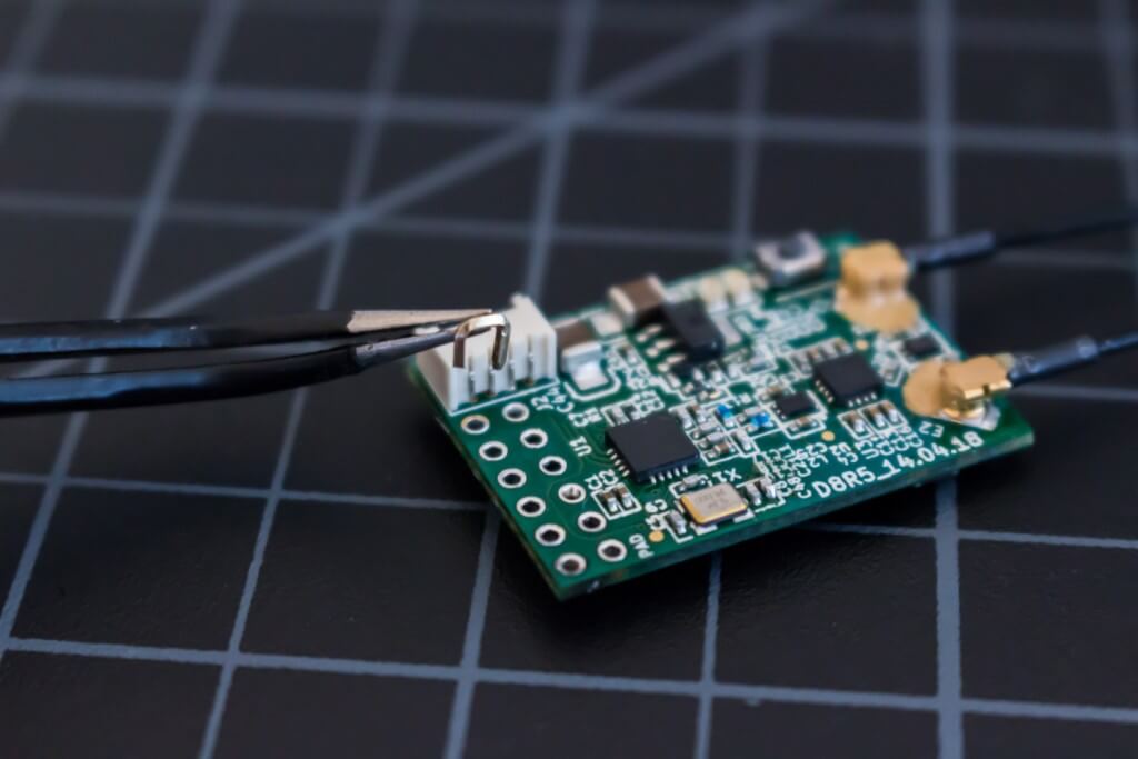
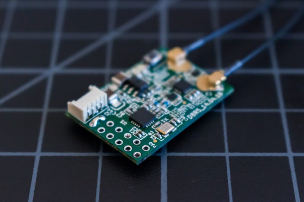
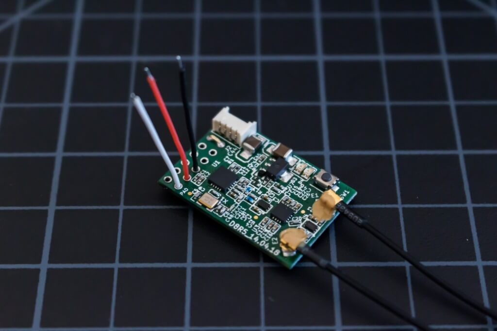
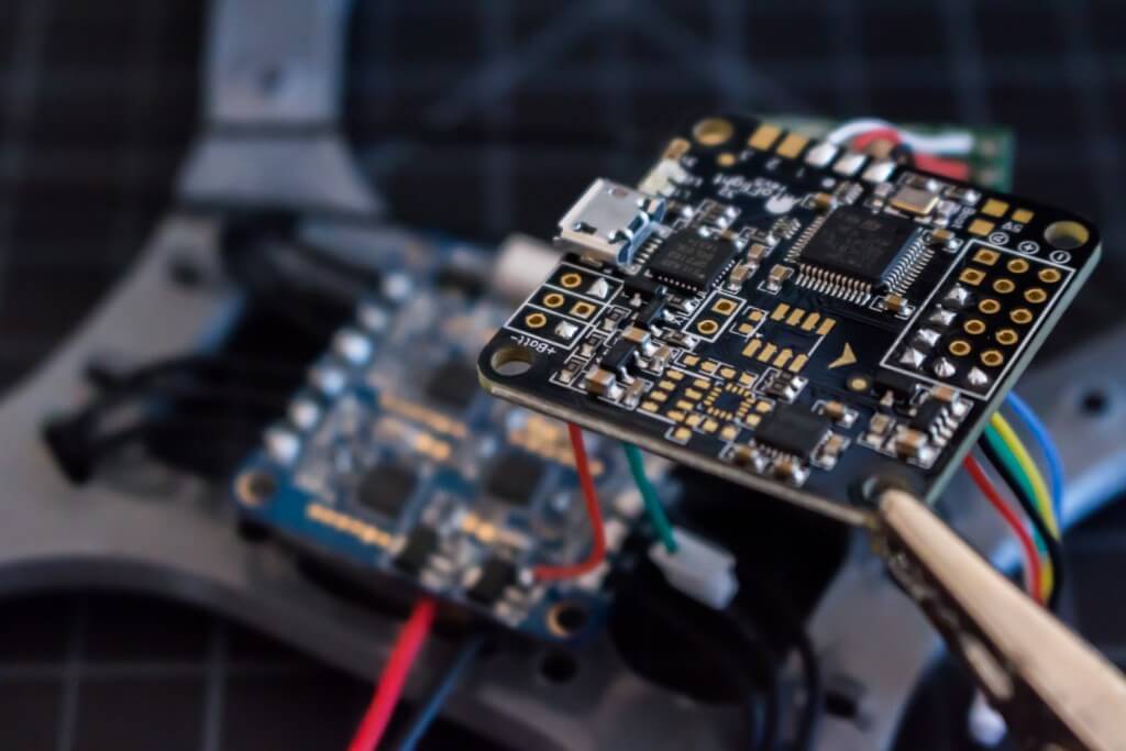
Remove the protective cover from the FrSky D4R-II Receiver. The D4R-II should be updated at this point if so desired. After the update is complete, carefully cut each of the pins and remove the black plastic retainer holding the pins together. Desolder each pin an place a jumper between channels 3 & 4 to enable CPPM. Connect three 3cm wires for power, ground and channel 1 (CPPM) to the channel 1 port on the D4R-II. Solder the other end of these cables to the power, ground and CCPM (3) pads on the Naze 32.
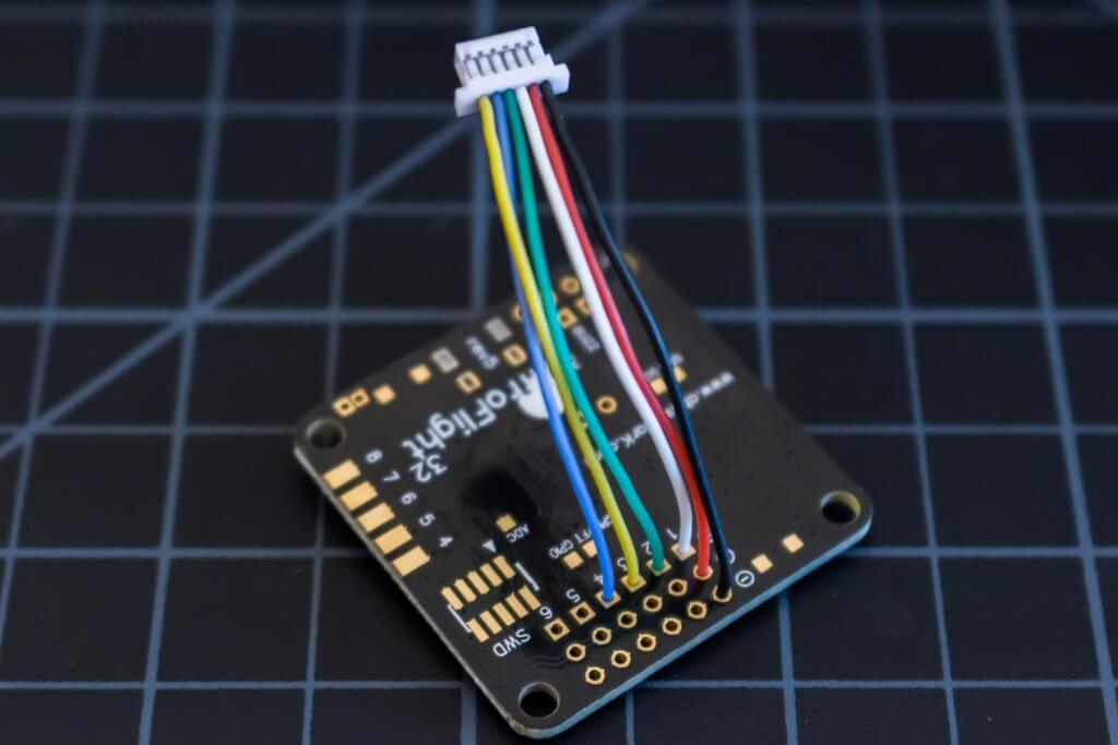
Unplug the DuPont cable from the 4in1 ESC and cut the signal wires to approximately 5cm from the connector that plugs into the board. Solder these ends to the Naze 32. Be sure to switch motor wires 3 & 4 as follows.
4in1 ESC: Naze 32:
M03 M02 ==> M04 M02
M04 M01 M03 M01

For FrSky telemetry, remove all but the TX wire from the FrSky provided telemetry cable and shorten the TX wire to approximately 3cm. Solder the TX wire to the telemetry pad on the Naze 32. Cut another 5cm wire from a scrap piece of wire and use it to connect to any pad on the 4in1 ESC shared with the positive battery lead. This wire is then connected to the positive battery pin on the Naze 32 for measurement of the battery voltage.
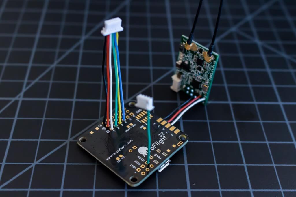
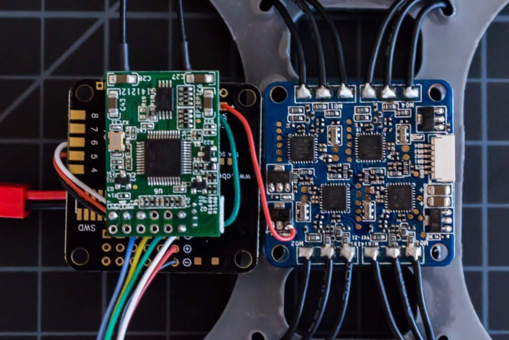
Place double-sided foam tape on the top and bottom of the D4R-II. Secure the D4R-II between the 4in1 ESC and the Naze 32. Bolt the Naze 32 and 4in1 ESC to the frame using the 8mm M3 nylon spacers, 20mm M3 nylon bolts and M3 nylon nuts. The M3 nuts are placed into the captive slots beneath the frame for ease of assembly and to prevent the nuts from coming loose. Before securing the roll bar to the top of the frame using two zip ties, update and program the flight controller with the Cleanflight user interface. Bolt on the props and you are ready to fly.

Hello from Sporthappy.
Have you had success with the RTF 4-in-1 ESC with this configuration? I’ve heard that they perform erratically with BLHeli and Oneshot with higher Kv motors, though the motors specifically noted were 4000kv. I bought the exact combination of components that you’ve used but haven’t had time to assemble it and I was wondering if I should just order different ESCs now or try the 4-in-1.