Flight
Super Simple Mini H-Quad V2.0
Flight Video:
Bill of Materials:
[Qty. 1] Super Simple Mini H-Quad V2.0 Frame[Qty. 1] CC3D Flight Controller
[Qty. 2] APC 5545E Electric Prop
[Qty. 2] APC 5545EP Electric Prop
[Qty. 4] MT-1306 10 3100KV Tiger Motor
[Qty. 1] USB Programmer
[Qty. 4] Turnigy Plush 6A ESC
[Qty. 1] 1000mAh 25~50C 2S Nano Tech LiPo
[Qty. 8] M2x12mm Bolt
[Qty. 4] M3x8mm Nylon Screw
[Qty. 4] M3 Nylon Nut
[Qty. 4] 5.6mm x 14mm M3 Nylon Spacer
[Qty. 4] Zip Ties
[Qty. 1] 16AWG Red Wire
[Qty. 1] 16AWG Black Wire
Assembly:
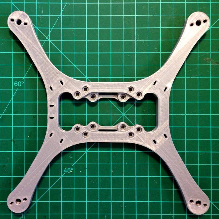
Each frame is 3D printed with plastic. The frames are printed with a semi-hollow infill. This core provides great strength without compromising the weight of the frame. At less than 80 grams the frame is light and extremely strong. Before assembling the quadcopter, clear any obstructions or loose plastic pieces from the holes of the frame.
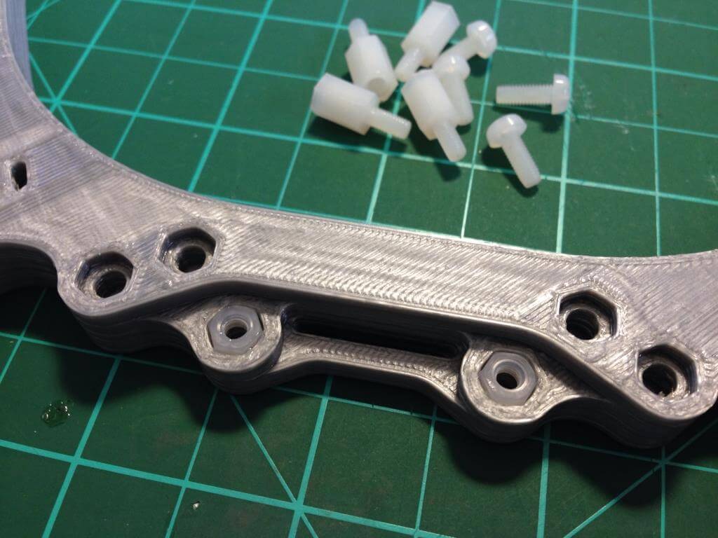
Glue four M3 nuts into the nut traps on the frame using a small drop of super glue (CA glue). Be sure not to fill the holes of the frame or apply glue to the threads of the nuts. Mounting holes are available for all standard fight controllers, including 45x45mm (KK2, Crius, Megapirates, etc..), 61x35mm (Ardupilot Mega), and 30.5×30.5mm (CC3D, PX4, etc…).
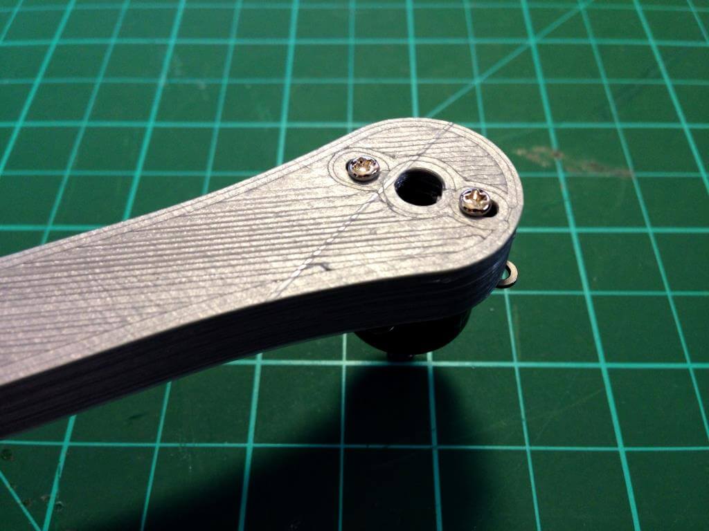
Use two M2x12mm bolts to secure the motors to each arm. The motor mounting slots support hole spacing from 12 to 15mm in diameter for motors such as the MT-1306 Tiger Motors or the cross mount of the Turnigy 1811 motors.
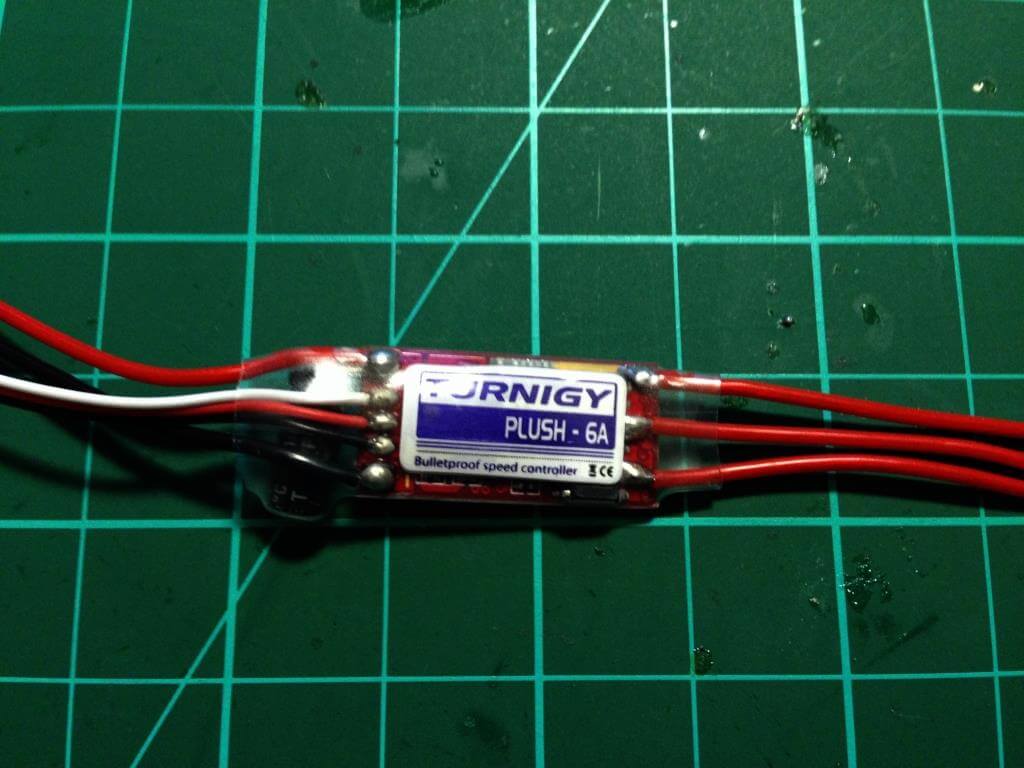
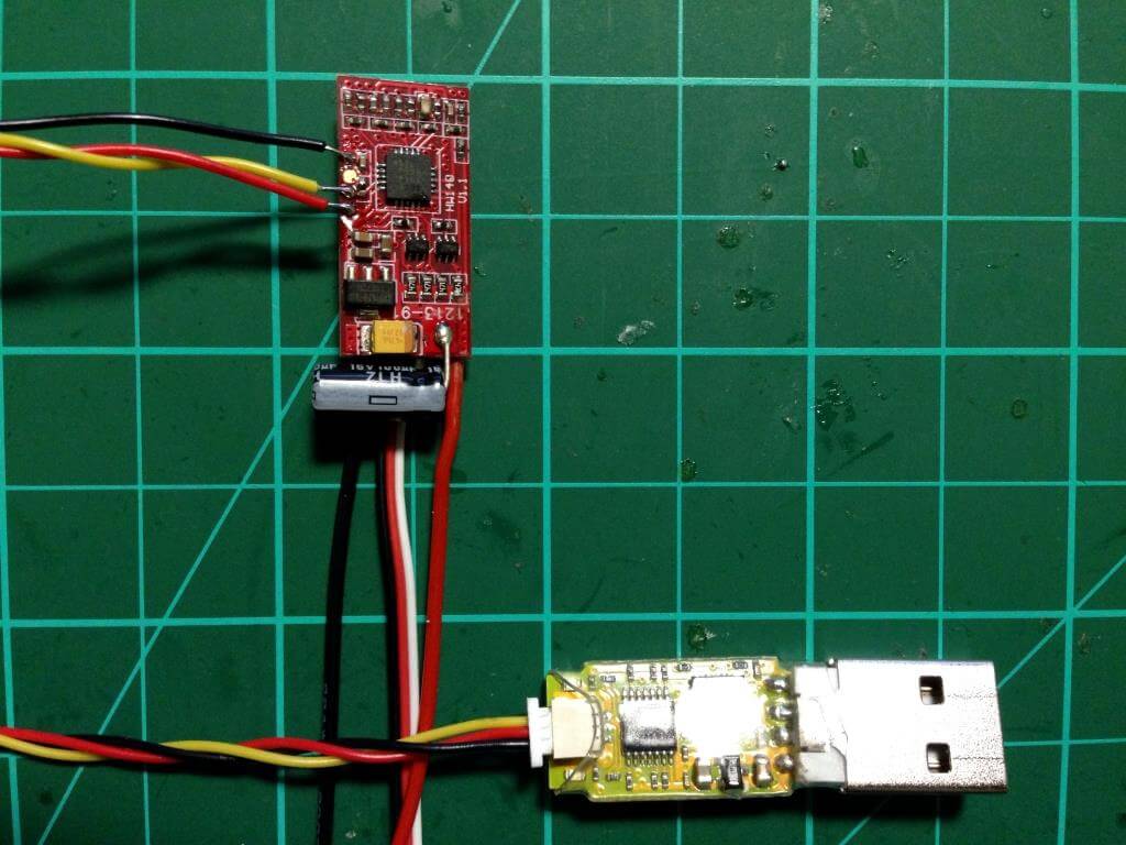
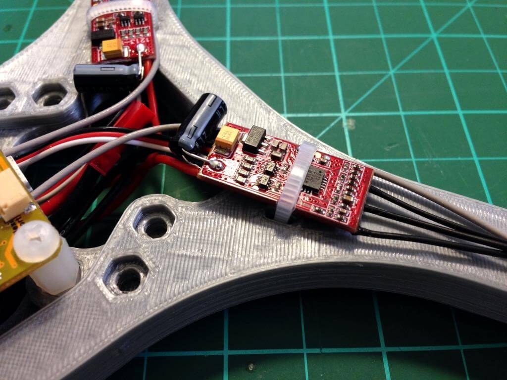
Standard 6A Turnigy Plush ESCs are recommended; however, the stock firmware is not well suited for multirotors. Replacing the firmware with BLHeli will improve the performance of the aircraft, but it is not entirely necessary. To replace the firmware, begin by removing the plastic heat shrink and sticker.
Using the USB programmer, connect the programming cable to the appropriate solder pads on the ESC. Pay close attention to the color of the wires and make sure they match the photo below on both the ESC and programmer side. Use BLHeli-Setup to flash BLHeli Multicopter (multi) firmware for the Turnigy Plush 6A ESCs. From the setup tool the ESC can be configured for a ppm min throttle of 1000 and a ppm max throttle of 2000. The remaining settings should be left at their default values. The min and max throttle can be calibrated from the radio, but the stick commands and tones to reach the calibration mode are rather complicated. I recommend setting the ppm min and max throttle for each ESC from the setup tool before removing the programming cable.
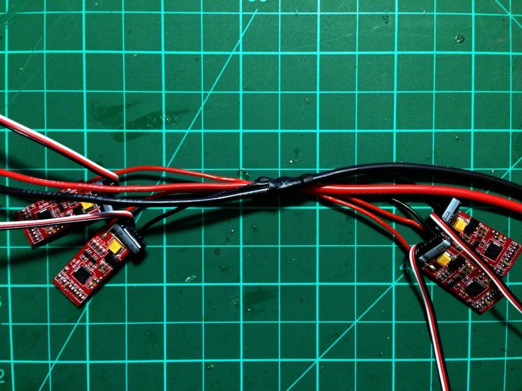
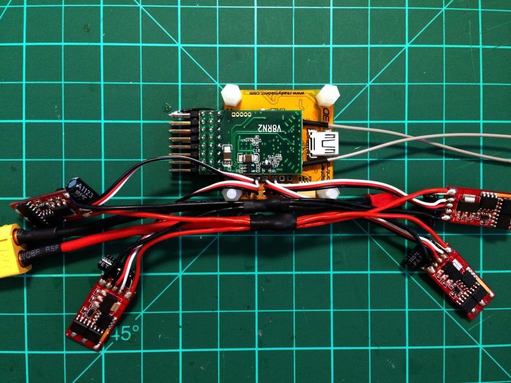
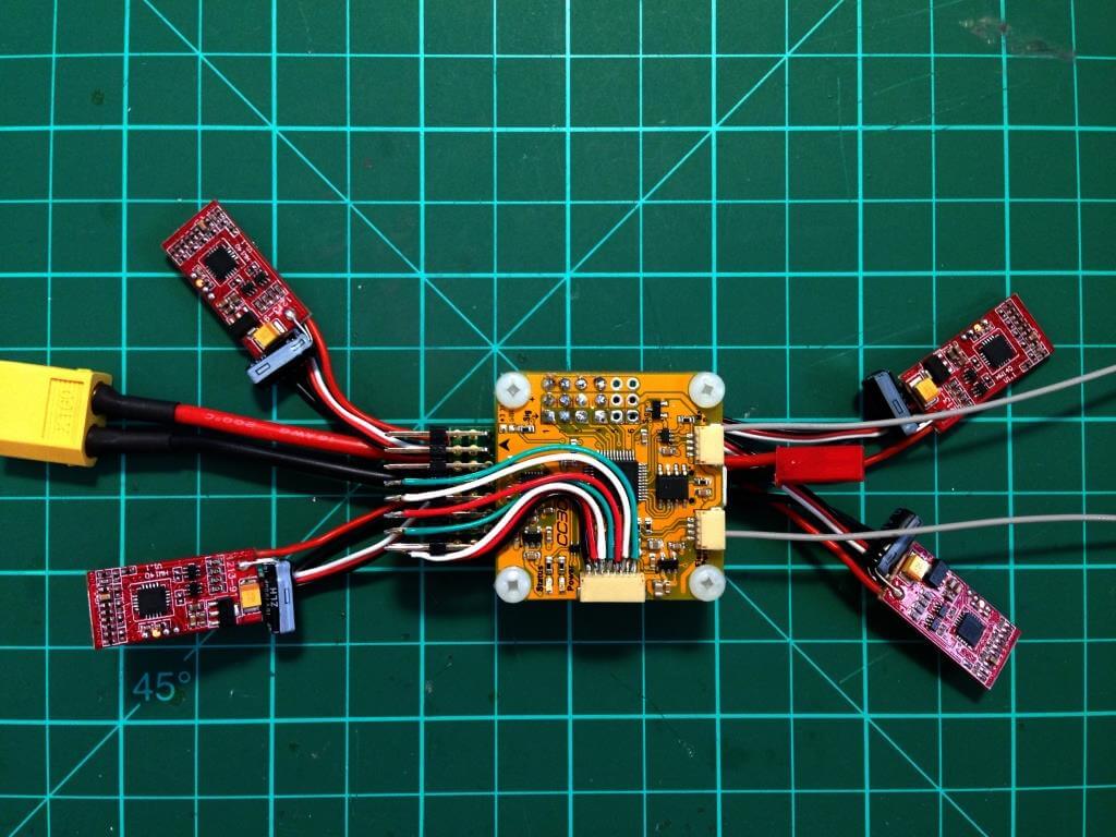
Align the four ESCs to the frame and cut the red and black power cables to the appropriate lengths so that they can join at the center of the frame. Be careful not to cut the cables too short! Cut two battery cables from the 16AWG wire and solder all four ground wires together with the battery cable. Do the same for the red power wires and add any lighting or accessory power cables to the harness before soldering the two halves together and covering them with heat shrink or electrical tape.
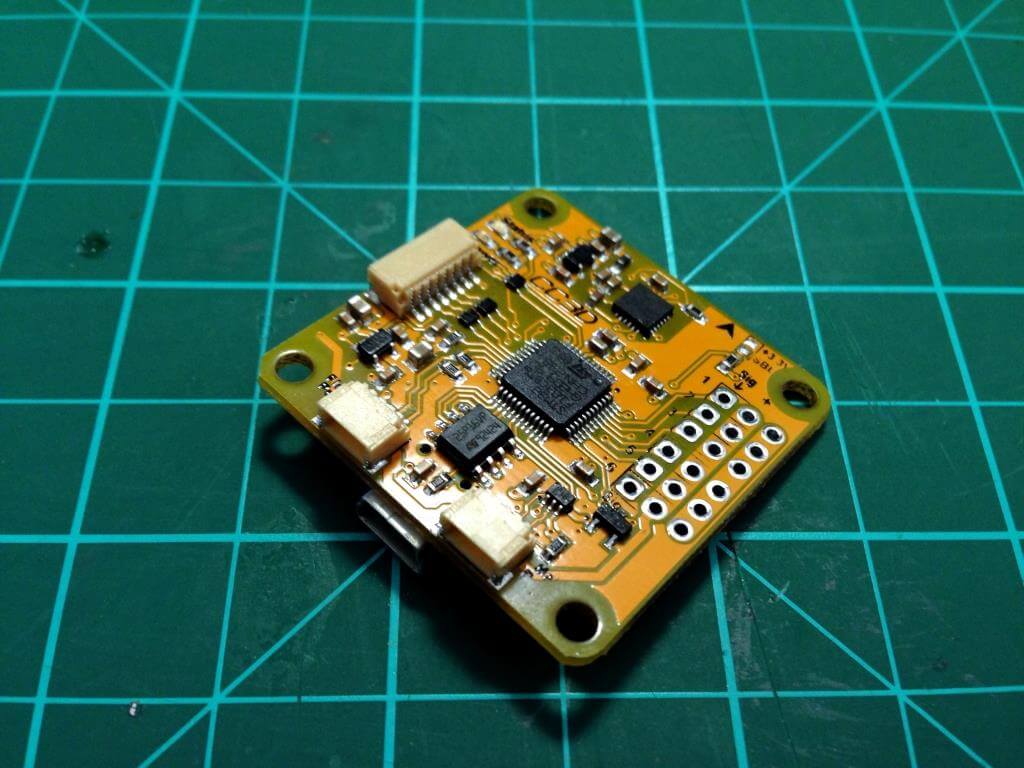
To keep the wires and cables clean, the header pins can be removed from the flight controller; however, this may result in damage to the flight controller if not performed properly. Do not remove the header pins unless you are experienced with doing so.
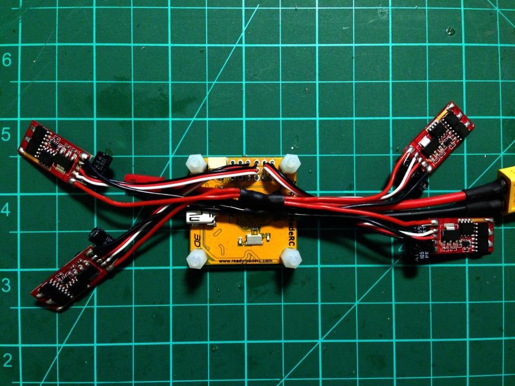
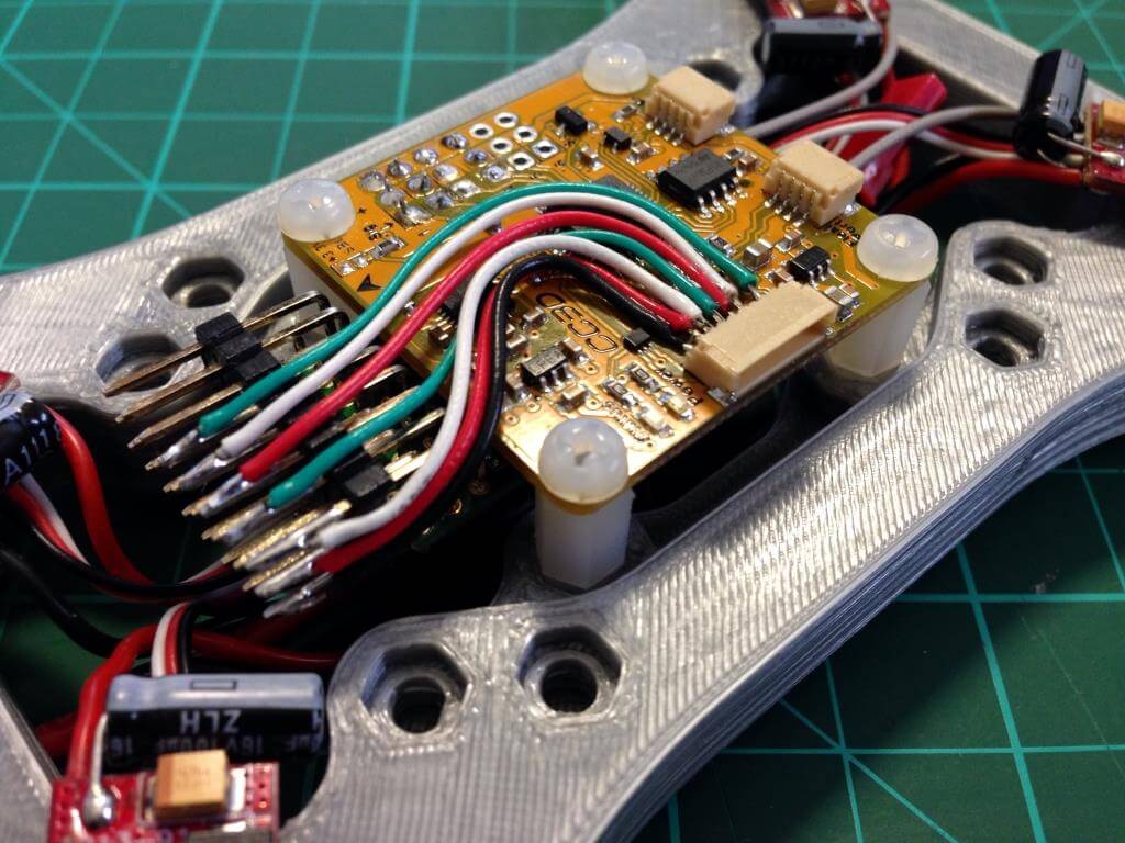
Once again, align the ESCs with the frame to determine the proper length of the signal wires. If the flight controller has no header pins, then the cables can be cut and soldered directly to the board, otherwise the cables need not be cut to length and they can simply be plugged into the respective ports.
The radio receiver can be secured to the bottom side of the flight controller using double-sided foam tape. It may be necessary to use a micro receiver or remove the plastic case from larger receivers. For this build I chose to use a FrSky V8FR receiver.
A ground and power cable from the CC3D must be shared with the receiver in order to provide the receiver with power. The cable included with the CC3D can be used to connect the receiver channels to the flight controller, or jumper cables can be soldered directly between the receiver and flight controller as depicted below.
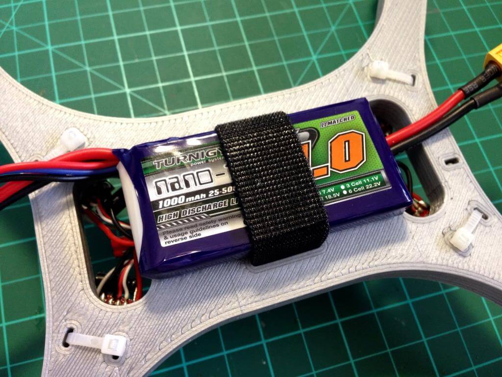
At this point the 3/4″ Velcro battery strap should be looped through the slots at the bottom of the frame and cut to wrap securely around the battery.
Using four nylon threaded spacers and four M3x8mm nylon bolts, attach the flight controller to the four mounting locations. Carefully situate the wiring harness above the battery strap and beneath the bottom of the flight controller.
Line up the ESCs on each arm and cut the motor wires to the appropriate length. The motor wires may be coated with resin, so be sure to use solder paste with a capable soldering iron to prepare the tips of each wire. Be sure to cross the wires of the ESCs so that motors 1 and 3 rotate clockwise while motors 2 and 4 rotate counter-clockwise.
With the frame complete check all connections and be sure that there is no continuity between the positive and negative terminals of your battery connector. Plug the flight controller into a computer to configure the settings and calibrate the sensors. Default setting will work fine with the CC3D, but I suggest that the rate P be reduced, rate I increased and attitude P increased depending on your style of flying. If all of the polarities and cables are checked, plug in the battery and test the rotation of the motors without props attached. If all is well, attach the props and you are all ready to fly!
OpenPilot Settings:
High value ==> more agile, low value ==> less aggressive
Attitude Responsiveness = 120 deg/s
Rate Responsiveness = 240 deg/s
Rate Yaw Responsiveness = 400 deg/s
Rate P = 25
Rate I = 40
Rate Yaw P = 35
Rate Yaw I = 35
Attitude P = 30
Attitude Yaw P = 20

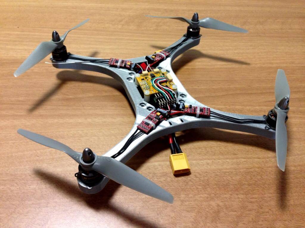
Thanks Adam for the great Micro-H Quad design and the awesome tutorial.
It took me a few weeks to build my little quad, after I received the 3d-printed frames.
Last weekend was my first real flight at the local sports ground and it was good fun.
A few crashes of course (since I’m a newbie) but no damage at all, which was really impressive.
Working on a camera solution to capture some footage.
Luke