Flight
Multiwii 1.9 Crius SE Flight Controller
The Crius SE Multiwii flight controller is a multicopter flight controller that uses Multiwii. The board can be purchased from GoodLuckBuy for $77.44. It performs well and comes packed with sensors and a FTDI basic programmer for an affordable price. This is a walk through of the steps I took to wire my Hexacopter and get it flying. Guides and additional information about this flight controller can be found at the rcgroups thread.
1 ) Solder bullet connectors to each speed controller.
2 ) Create a power distribution cable with six positive leads and six negative leads each with bullet connectors.
3 ) Wire two futaba terminals for auxillary power from the power distribution.
4 ) Wire and reverse wire the motors to each speed controller in accordance with the correct rotation of each motor.

5 ) Wire the futaba leads from each speed controller to the Crius board as follows:
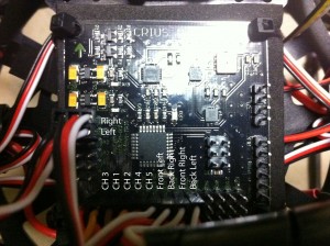
6 ) Download Arduino v0023 and MultiWii 1.9.
!!REMOVE ALL PROPS DURING PROGRAMMING AND TESTING!!
7 ) Plug the FTDI adapter into the Crius and your computer.
8 ) Launch Arduino and open “MultiWii_1_9.pde” from MultiWii 1.9.
9 ) Select the “config.h” tab and uncomment (Remove the “//”) from the following lines of code:
“#define HEX6X” This will define the type of aircraft you will be using the board with
“#define YAW_DIRECTION 1” If the rotation of your props is opposite then choose “#define YAW_DIRECTION -1”
“#define I2C_SPEED 400000L”
“#define INTERNAL_I2C_PULLUPS”
“#define A0_A1_PIN_HEX” This will allow you to operate the hex with a standard receiver, no ppm sum signal
“#define RCAUXPIN8” or “#define RCAUXPIN12” if you want an additional mode switch, requires 6 channels
“#define FREEIMUv035_BMP // FreeIMU v0.3.5_BMP”
10 ) Save these modifications and upload the firmware to the board.
11 ) Close Arduino and launch MultiWii
12 ) Select the COM port for you FTDI adapter and press “start” and then “read”
13 ) Adjust your PID settings and modify your auxilary switches.
14 ) Calibrate the accelerometer on a level surface, the blue light will flash during this process.
15 ) Calibrate the magnetometer by rotating the board 360 degrees along each axis, you will have 30 seconds to do so as indicated by the flashing blue light on the board.
16 ) Bind your transmitter to the receiver and power on all of your equipment.
17 ) Check that your sticks are all centered around 1500, if not adjust the trim on your transmitter.
18 ) Check that the correct orientation including pitch and roll are indicated.
19 ) Remove the cable, attach the props and test fly. It may be a good idea to tether the mutlicopter to the ground for the first flight just to be sure that your wiring hasn’t resulted in any reversed motors. If it doesn’t try to flip then remove the tether and proceed, otherwise check your wiring connections between the motors and escs.
20 ) Adjust the PID setting to maintain stable oscillation-free flight.
21 ) Trim the accelerometer and gyro according to this chart:
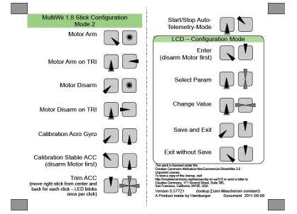
22 ) Enable the barometric pressure sensor and magnetometer one at a time as you test and adjust the settings for each.
These are the PID settings that I am currently using, however, I have not completely tuned and adjusted all parameters:
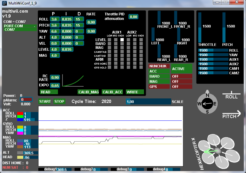
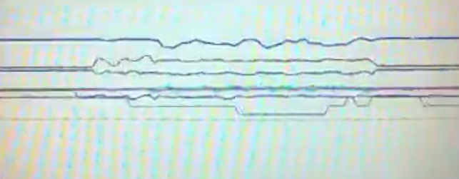
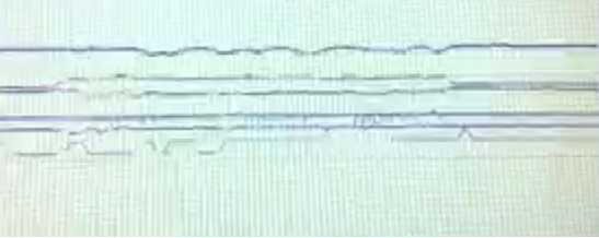
Be sure that your props are balanced and the flight controller is well isolated from vibrations. In the following pictures you will see the amount of noise caused by vibrations without and with a foam pad under the board. Unbalanced props will have an even worse effect and cause the platform to randomly wobble and oscillate in flight.
