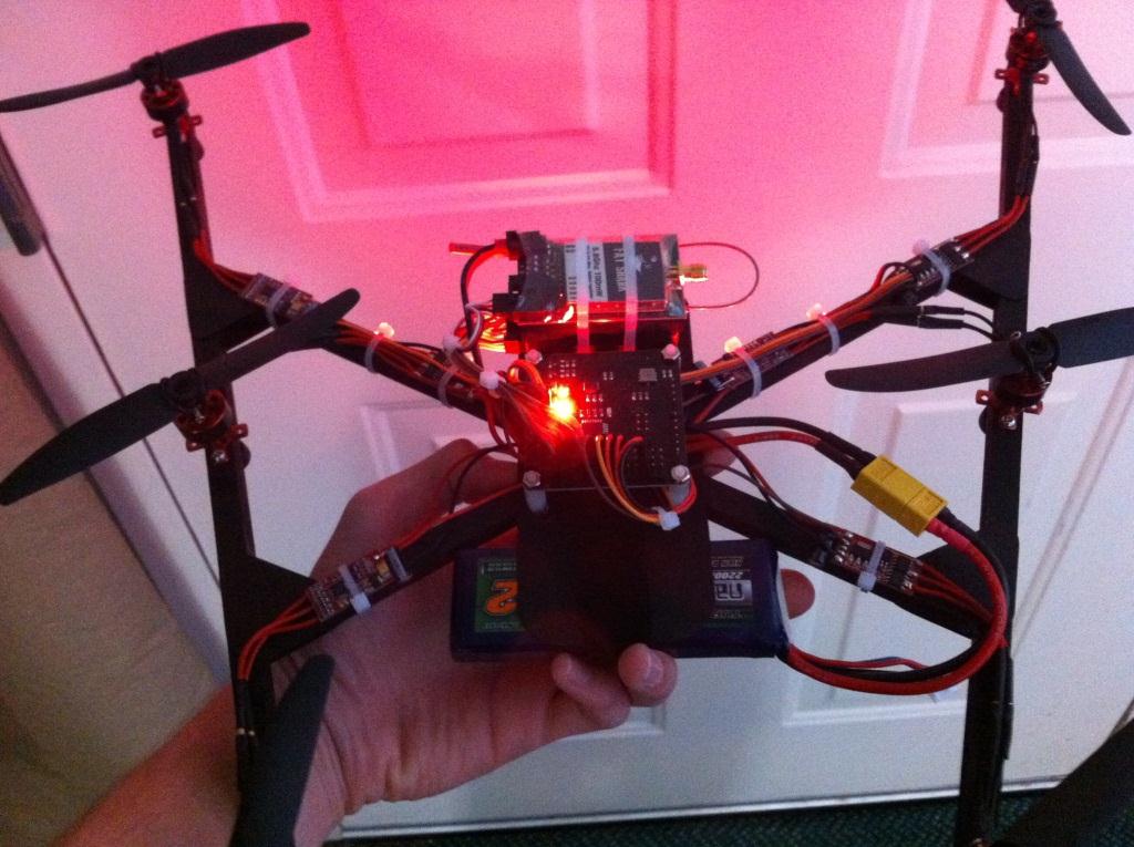
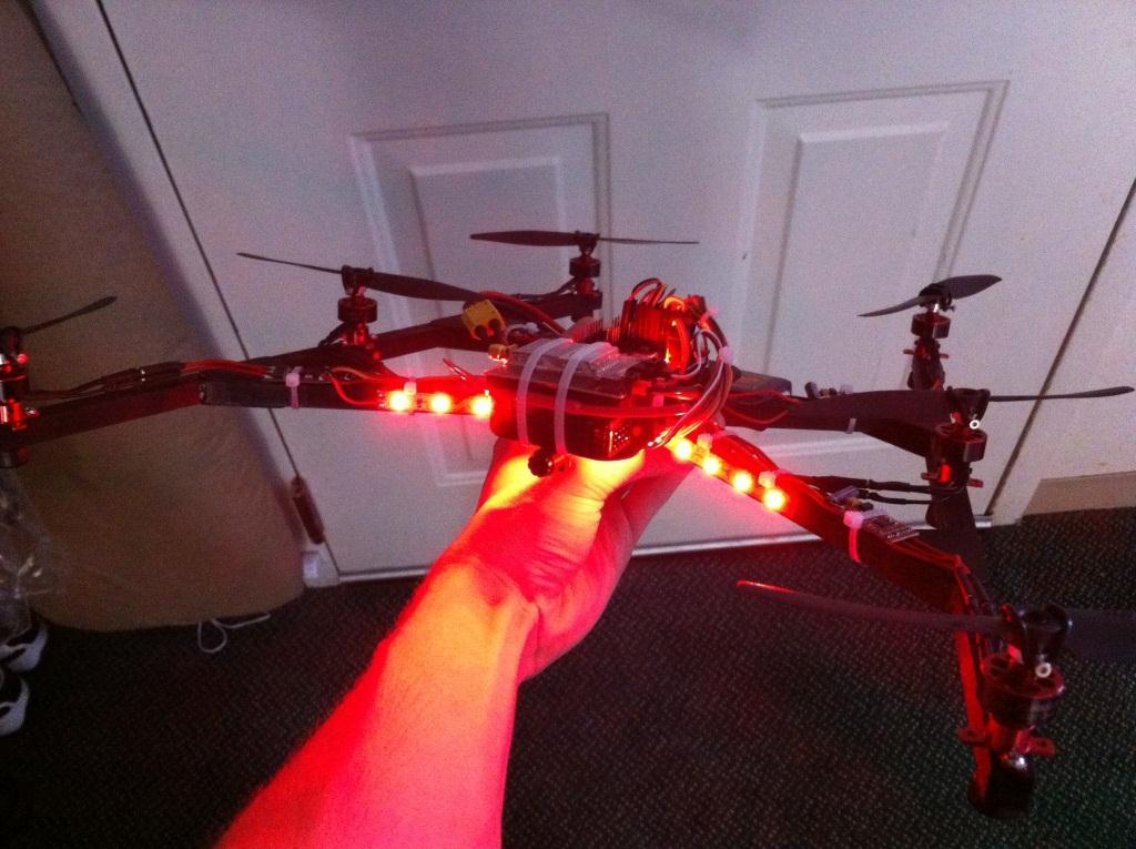
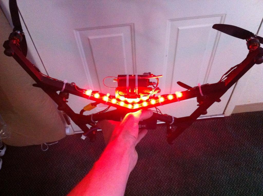
Flight
V6 FPV Multicopter
Bill of Materials
[Qty. 3] 3/8″ Basswood Square Rods [Qty. 1] 1/32″ Birch Plywood Sheet [Qty. 1] M2x8 Screws [Qty. 1] Cable Ties [Qty. 1] 20AWG Red Wire [Qty. 1] 20AWG Black Wire [Qty. 6] 2900kv Brushless Outrunner [Qty. 6] Plush 6A ESC [Qty. 1] 26AWG Servo Wire [Qty. 1] Servo Terminals [Qty. 1] Male to Male Servo Leads [Qty. 1] KK2 Flight Controller [Qty. 1] 2200mAh 2S Nano-Tech Lipo
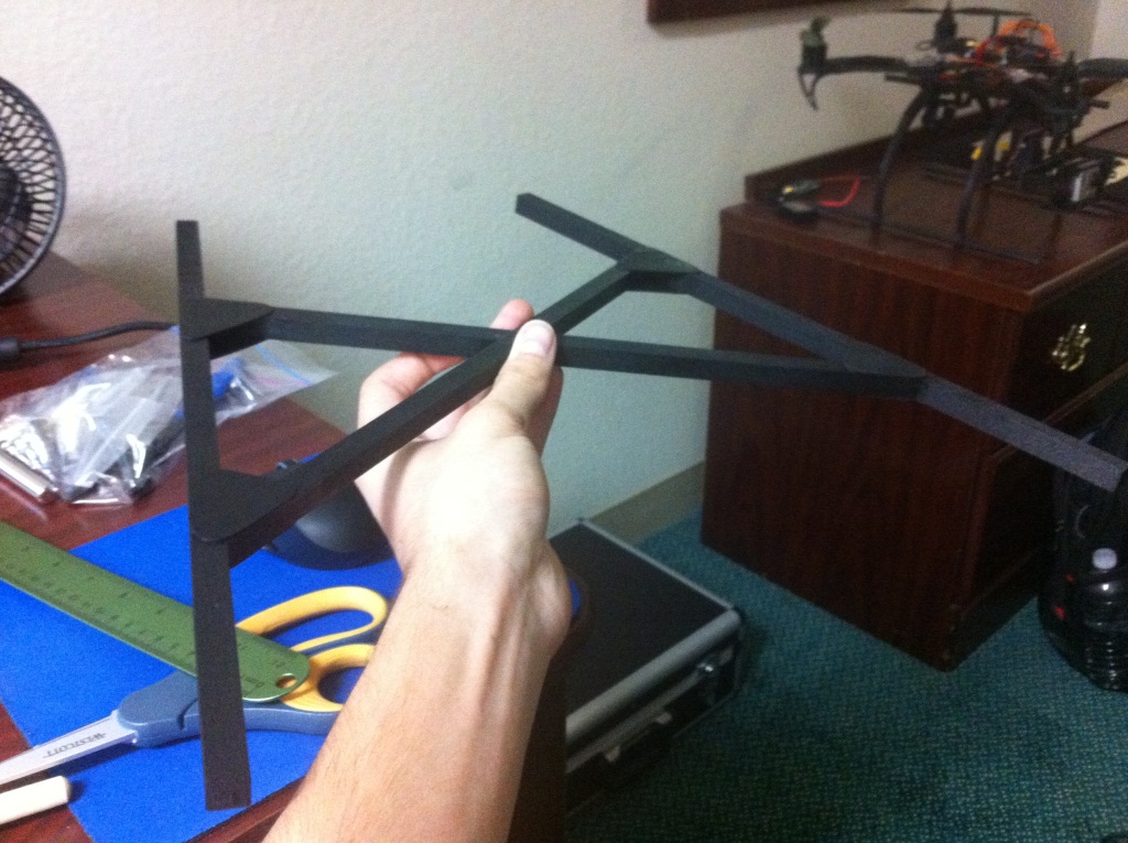
To construct the frame I began by cutting two 13″ arms from the 3/8″ basswood rods. The arms sweep out 14.5 degrees from the center placing the rear two motors about 7.25″ apart and the front two motors about 13.5″ apart. The cross arms are approximately 11″ long and they have been notched to rest across each other. It is best to cut and align the outer arms to a template before measuring up and cutting the inner cross arms.
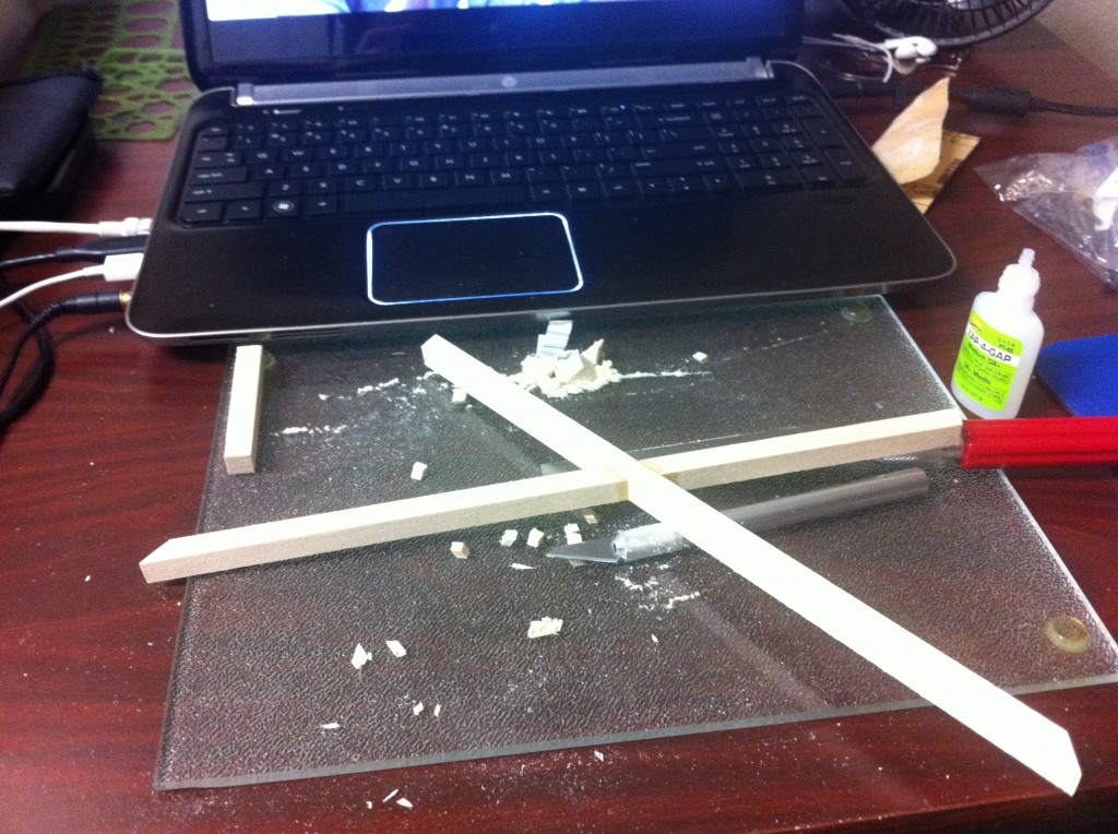
The center plate was cut to about 2.5″ x 5.5″ and slotted to mount the battery and radio gear. Before mounting the motors and ESCs I removed the servo wire of each ESC and replaced it with a longer wire. All three of the connections were soldered to the first ESC, but the reamaining ESCs only have a signal wire. I also soldered the supplied bullet connectors to each ESC and motor. The motor mounts are fixed to the frame with two M2x8 screws. The correct rotation for the motors is described in the KK2 motor layout.
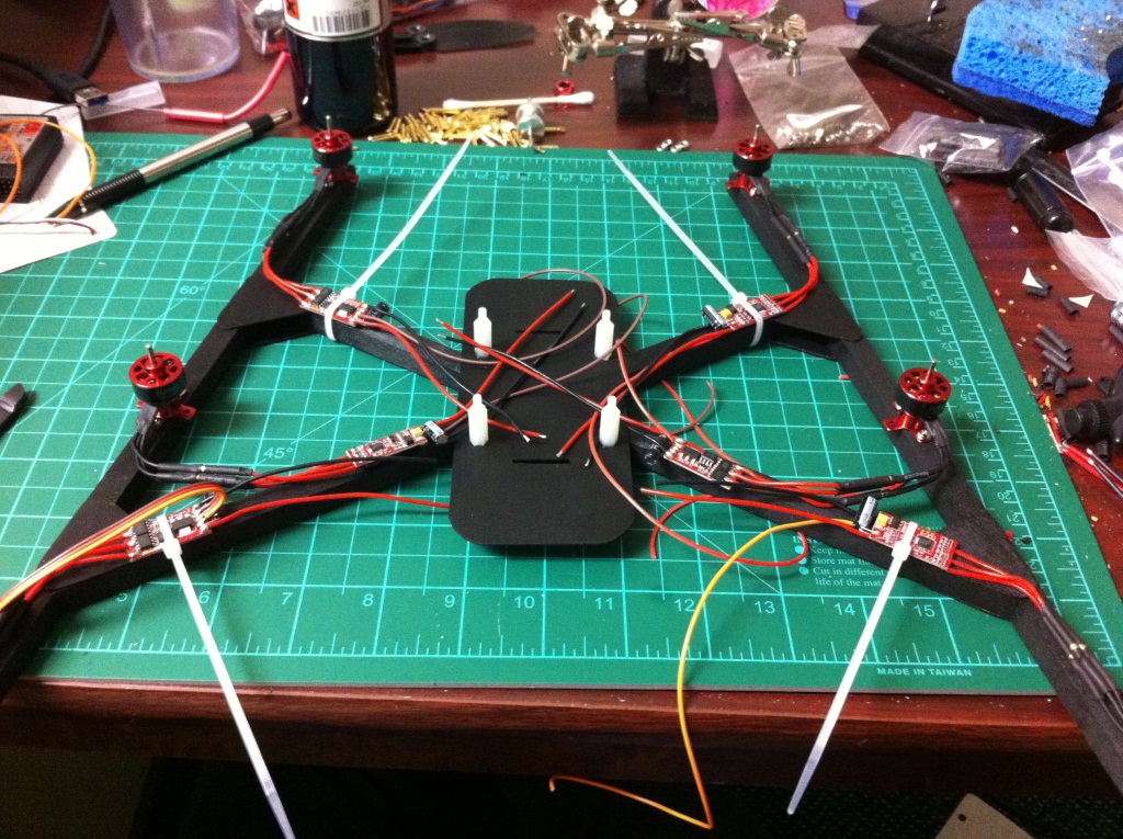
The power wires for the front two motor ESCs are daisy chained to the middle motor ESCs to clean up the wiring. In order to support the current of both ESCs I replaced the power wires of the middle motor ESCs with 20AWG wire.
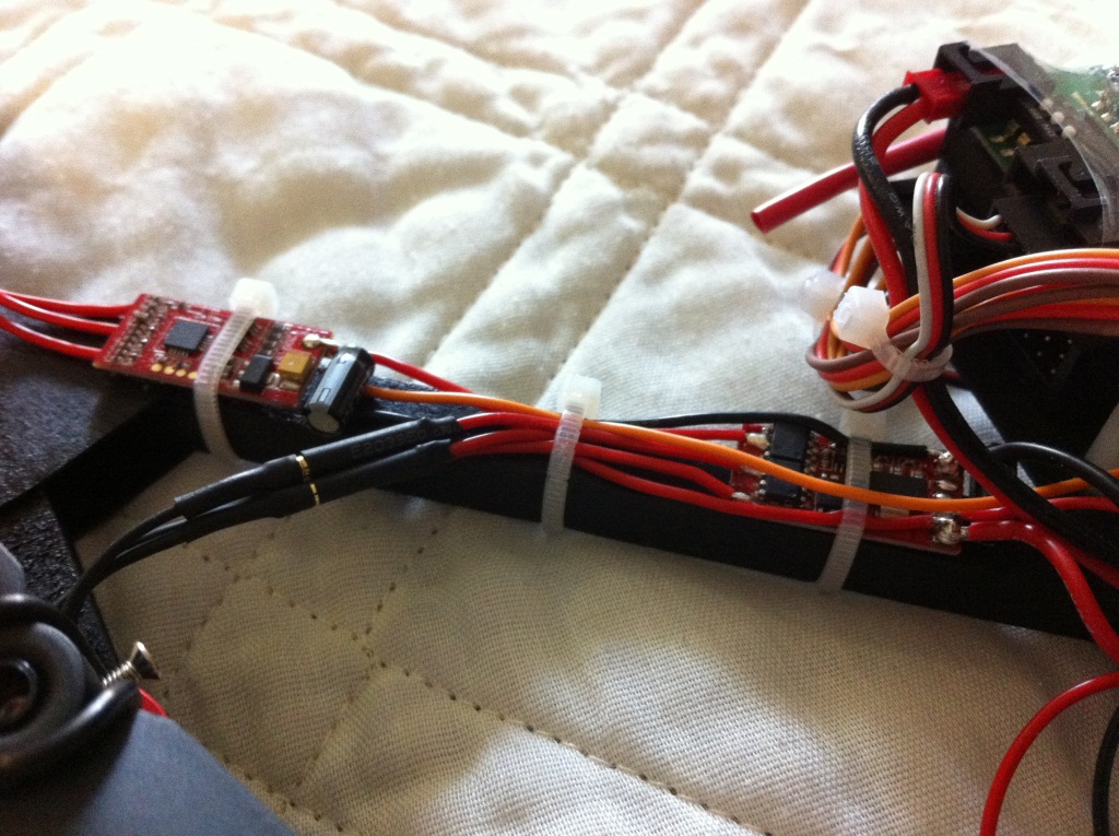
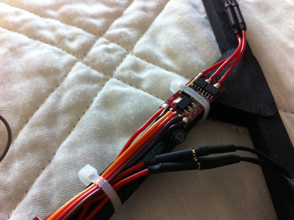
As shown below, only on the first motor ESC are all three servo wires routed back to the flight controller. The remaining ESCs have only a single signal cable routed back to the flight controller. Since the stock leads aren’t long enough, it is much easier to only solder an extended signal wire where necessary.
The center of the flight controller is positioned just behind the middle motors so that the center of the frame is aligned across the sensors (mounted at the top of the board).
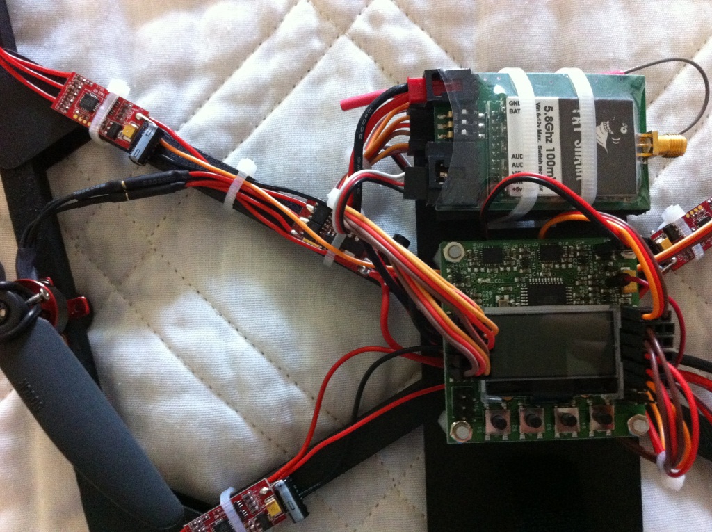
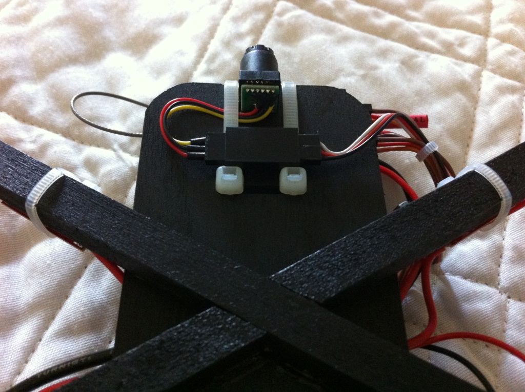
I mounted a Pico-Wide FPV Camera beneath the front plate of the frame. The fatshark 5.8GHz 100mW video transmitter is secured on top of the 8-channel 2.4GHz receiver.
Finally, the 2200mAh 2S LiPo was secured beneath the rear of the center plate using a Velcro strap. The props are mounted with the supplied prop savers as they are the easiest and most well balanced method of mounting the props. Flight time with the 2200mAh LiPo is approximately 13 minutes.
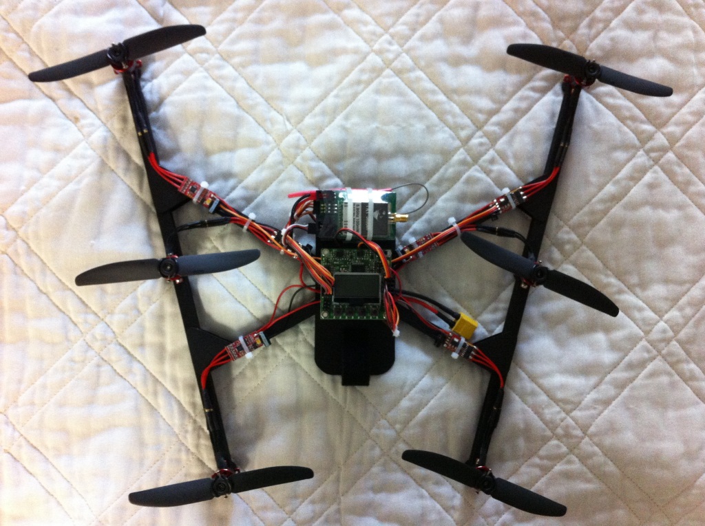
I also modified the V6 mixing for better yaw control. The default settings cause the aircraft to sweep very wide as it yaws. Imagine a point at which the arms intersect to the rear of the frame; with default settings it is as if the aircraft yaws about this point. By modifying the rudder mix the yaw control is improved, but it remains quite slow.
CH1 Rudder: 100
CH2 Rudder: 71
CH3 Rudder: 42
CH4 Rudder: -42
CH5 Rudder: -71
CH6 Rudder: -100
My current PID settings are as follows (These may still need some adjustment):
Aileron & Elevator
P Gain: 60 P Limit: 10
I Gain: 30 I Limit: 10
Rudder
P Gain: 150 P Limit: 20
I Gain: 50 I Limit: 10
After spending an hour adjusting the auto-level settings, I arrived at the conclusion that the control algorithms of the KK 2 are not designed for true “auto-leveling” so much as they are for drift compensation. The algorithms are not calculating the precise angle of the controller, but they are instead compensating for acceleration due to gyro drift. This results in a huge amount of lag compared to that achieved through true auto-leveling with an AHRS algorithm. I eventually installed a MWC Crius MultiWii flight controller with a custom V6 mix. The flight performance far exceeds that of the KK2 in both auto-leveling and yaw authority. A tutorial for writing custom motor mixes for MultiWii can be found here. I also added some LEDs so that it looks like a Cylon Raider 😉
