Flight
Low-cost Image-assisted Inertial Navigation System for a Micro Air Vehicle
Abstract:
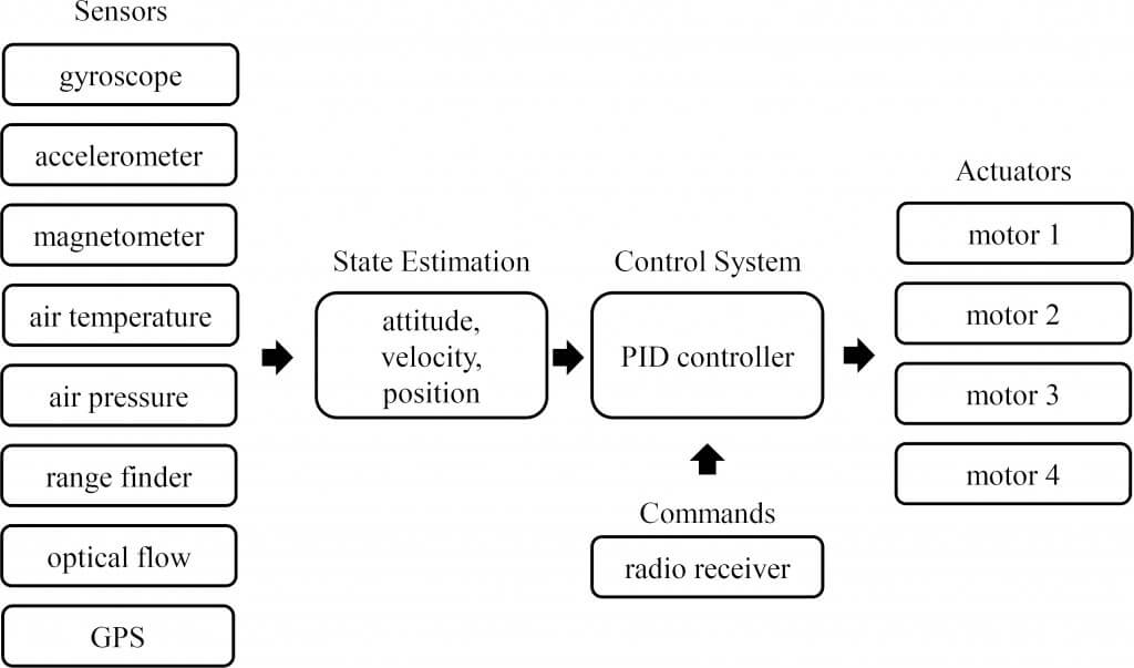
The increasing civilian demand for autonomous aerial vehicle platforms in both hobby and professional markets has resulted in an abundance of inexpensive inertial navigation systems and hardware. Many of these systems lack full autonomy, relying on the pilot’s guidance with the assistance of inertial sensors for feedback and stability. Autonomous systems rely heavily on the use of a global positioning satellite receiver which can be inhibited by satellite signal strength, low update rates and poor positioning accuracy. For precise navigation of a micro air vehicle in locations where GPS signals are unobtainable, such as indoors or throughout a dense urban environment, additional sensors must complement the inertial sensors to provide improved navigation state estimations without the use of a GPS. By creating a system that allows for the rapid development of experimental guidance, navigation and control algorithms on versatile, low-cost development platforms, improved navigation systems may be tested with relative ease at reduced cost. Incorporating a downward-facing camera with this system may ultimately be utilized to improve vehicle autonomy in denied-GPS environments.
Motivation:
Few existing commercial solutions allow for direct implementation of high-level estimation and control algorithms. A product support package developed by students at Embry Riddle Aeronautical University has been available for the Ardupilot Mega 2.0 since November of 2012, but the Ardupilot Mega hardware is outdated and incapable of handling complex computationally-intensive algorithms.
The PixHawk Development team of ETH Zurich offers a state-of-the-art PixHawk autopilot system; however, until recently no solution existed to seamlessly integrate high-level control systems directly with the PixHawk hardware.
![]()
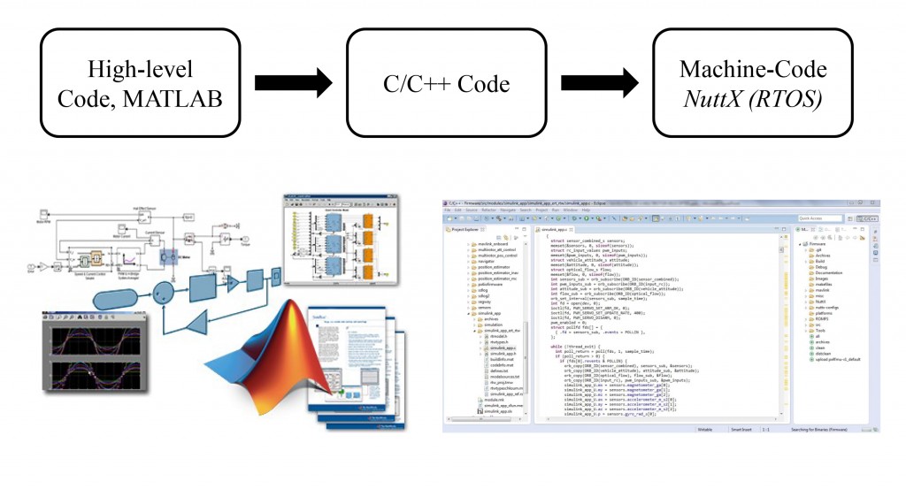
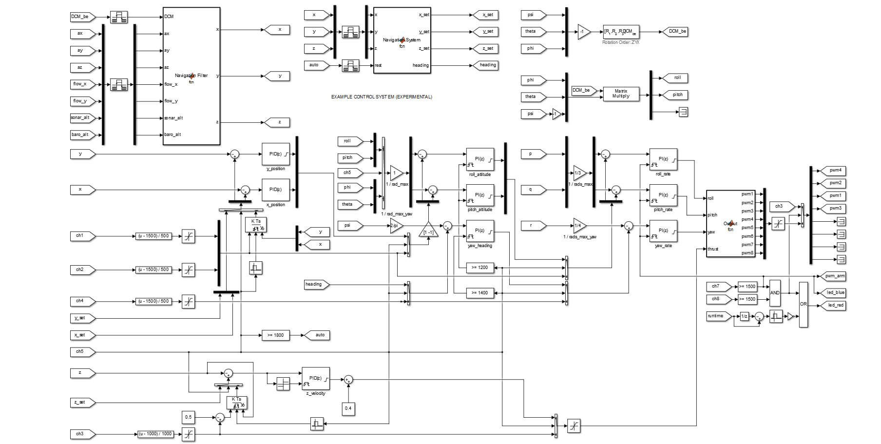
Although a readily available solution to this problem has not existed until now, the architecture of the open-source PX4 autopilot system allows for implementation of such a solution with relative ease. With this software, controls engineers need not possess a thorough understanding of the underlying software architecture. This eliminates the need to write embedded C/C++ and machine code, allowing engineers to take algorithms straight from a high-level block diagram in Simulink directly to the hardware. The process is a simple and repeatable method for testing complex estimation and control algorithms at a much reduced cost.
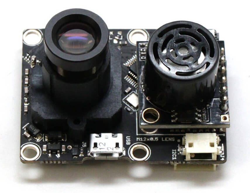
The PixHawk platform also supports advanced computer vision systems for optical navigation purposes, such as the low-cost PX4FLOW optical flow module.
Construction:
Preliminary Design Concept:
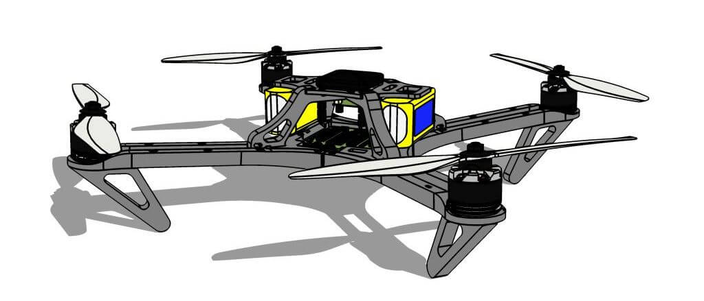
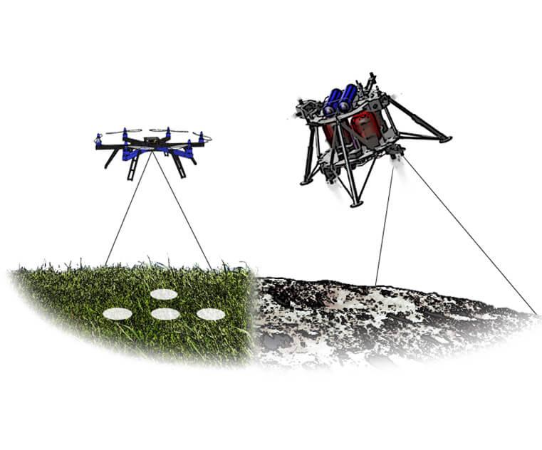
A miniature quad copter is selected for this particular application due to the relative ease with which it may be assembled and modeled, as well as the simplicity of its design and maneuverability. The basic airframe is designed to enclose and protect all essential electronics. The airframe is 3D printed from PLA plastic filament. It is small enough to navigate tight spaces and yet light enough as to not easily become damaged in a collision.
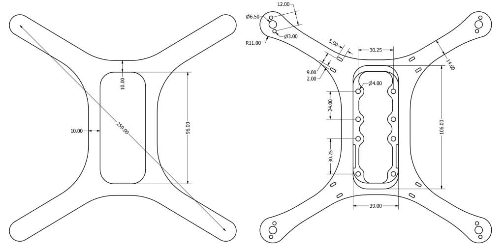
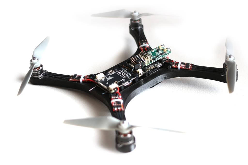
Finalized Design:
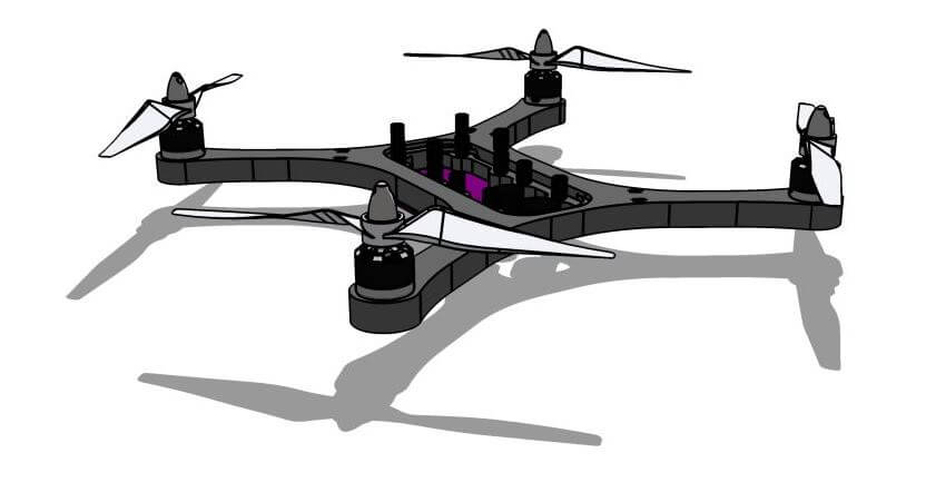
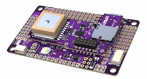
The system includes the PX4 autopilot controller along with the PX4FLOW vision system and a 1000mAh battery capable of supplying nearly ten minutes of power. The collective mass of these components on the fully assembled vehicle is approximately 250 grams, giving the vehicle nearly a 2:1 thrust to weight ratio.
System Dynamics and Control:
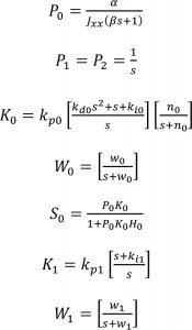
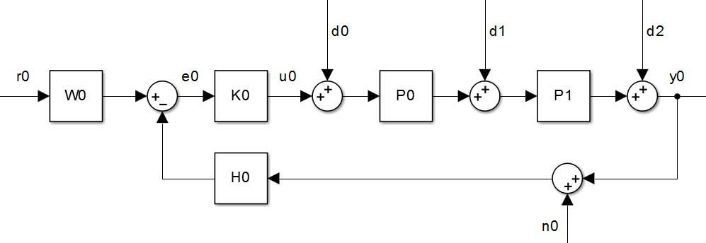
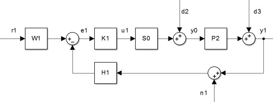
A quadcopter is inherently unstable, thus the vehicle attitude and rate of rotation must be controlled with a feedback control system. To design a proper controller, all vehicle dynamics are modeled using Simulink. For simplicity, the system dynamics are first isolated to separate axes and independently modeled. The plant P0 is represented by the transfer function from the normalized roll command to the angular roll acceleration where α is the maximum torque, Jxx is the inertia and β is the mechanical motor constant. P1 and P2 are both integrators modeling angular roll velocity and angular roll position. Sensor dynamics H0 and H1 are treated as a unity gain.
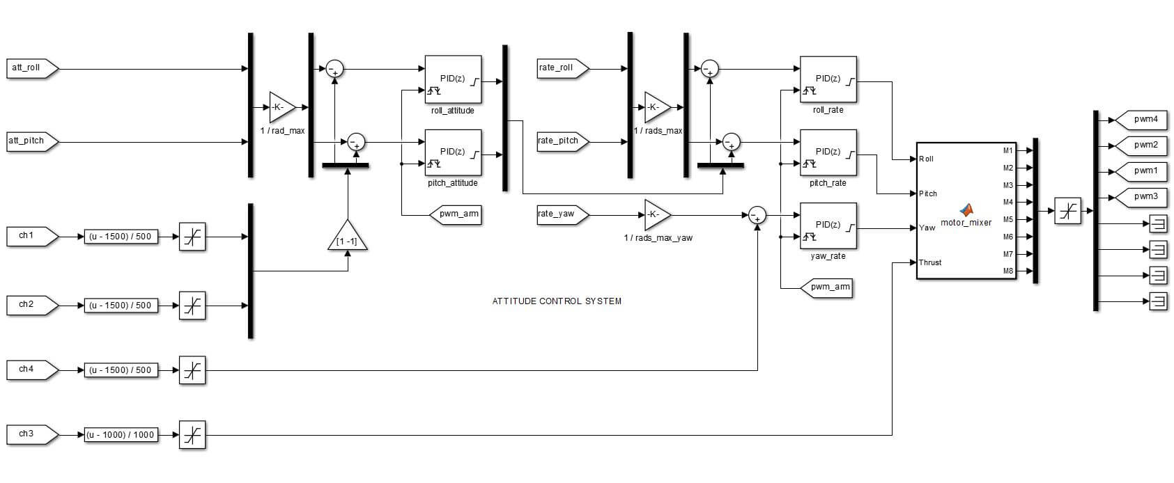
Inner-Loop Rate Controller:
Outer-Loop Attitude Controller:
A more complex model is implemented using the Simulink 6-DoF Quaternion Fixed-mass Equations of Motion aerospace block. This allows for ease of simulation of all non-linear system dynamics. A brushless motor model is used to resolve the rotor velocity, which is then related to the thrust of each rotor. The forces and moments are resolved in the body-frame where Newtonian physics describe the acceleration, velocity and position of the vehicle. A quaternion rotation algorithm then resolves the vehicle dynamics in the flat-earth reference frame.
Non-linear Model:
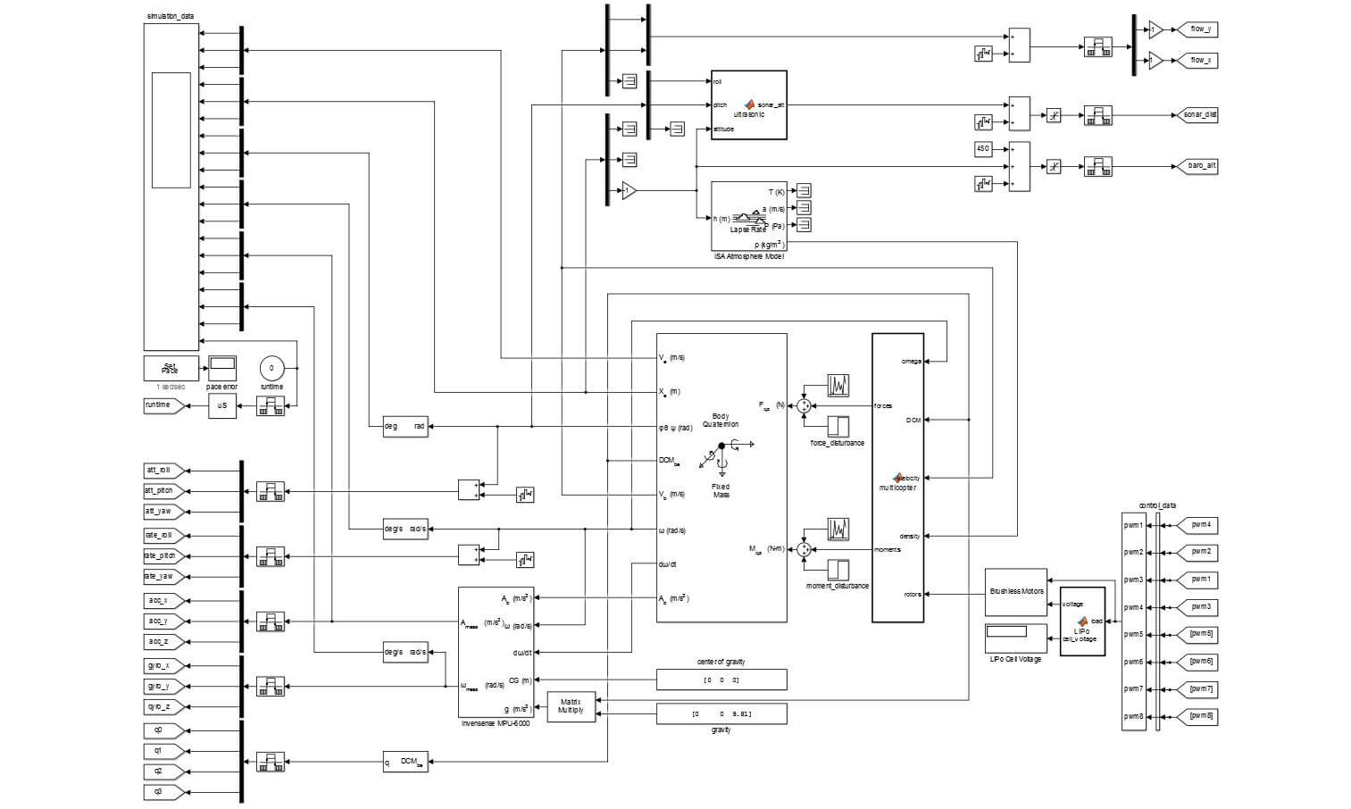
Complete Attitude Control System:
Optical Navigation:
One of the greatest obstacles to implementing an optical navigation system is the system state estimation of the vehicle position. The PX4 optical flow sensor estimates body-frame velocity and ground distance. These estimates are fairly accurate; however, optical navigation requires Earth-frame position and velocity states.
Integrated Optical Flow Velocity Estimates:
Improved Earth-frame position estimates are provided by a ten-state Kalman filter. These estimates are processed by the guidance and navigation system which issues reference commands to the outer-loop position controller.
Kalman Filter Position Estimates:
Experimental Optical Navigation System:
Conclusion:
The objectives of this project have been met by the successful design and testing of a low-cost image-assisted quadcopter. The applications for such a small and maneuverable vehicle are considerable. In addition, the software architecture now exists to utilize the PixHawk autopilot platform for rapid development and testing of complex experimental estimation and control algorithms using Simulink. Further effort is necessary to develop the optical navigation system to a usable state. Current models function well in computer simulations, but imprecise models of sensor dynamics and measurement uncertainty must be enhanced to match the true system characteristics.
Download Complete Thesis: