Rapid Prototyping
V2.0 Printrbot + Upgrades
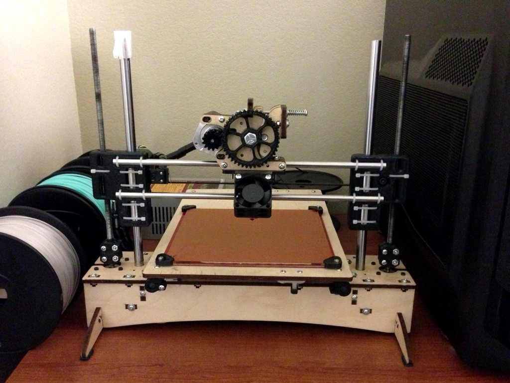
Several months after completing my original Printrbot + Upgrades, I am now introducing the latest version of my improvements. These new components address several problems with the original upgrades and they are also much stronger, easier to assemble and they require far less material and print time.
New Features:
- Minimal hardware required – assembly requires 22 zip ties and nothing more.
- Fewer pieces – the bridge consists of only two pieces instead of four halves.
- Easy access – the parts are more open for easy access to clean or replace the linear bearings.
- Increased strength – components are now much stronger where they need to be.
Fixes:
- Raised bed levelers to prevent interference with y-axis pulley.
- Improved bearing tolerances (Should work with LM12UU or LME12UU linear bearings)
- Thicker extruder mounting plate, no warping.
- Increased clearance between extruder mount and heated bed.
- Extended motion of the extruder mount with an adjustable x-axis end stop.
- Better alignment of the adjustable z-axis end stop with added nut trap.
Notes:
- Designed for GT2 belts and pulleys.
Downloadable model here.
Assembly Instructions
Begin by cleaning excess plastic from the holes and corners of each part with a hobby knife. Assemble the three piece motor mount by aligning the pieces into the slots on the back of the left bracket. Only apply superglue to these three pieces, do not glue the completed motor mount to the back of the bracket. Completely assemble the six piece extruder mount with superglue.
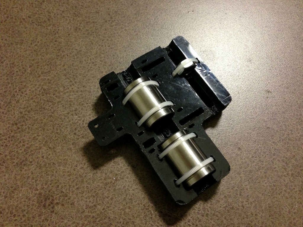
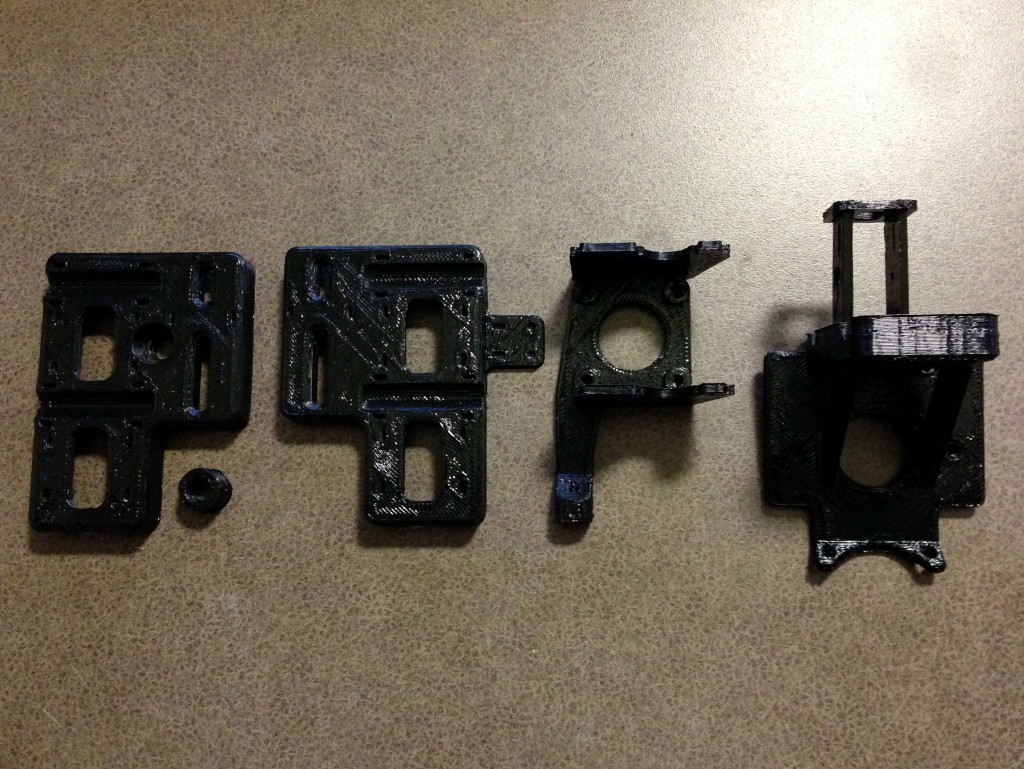 Assembly the right bracket by securing the linear bearings and z-nut with five zip ties. Insert the pulley bolt and 10mm spacer before bolting the pulley into place.

Assembly the left bracket by securing the linear bearings and z-nut with five zip ties.
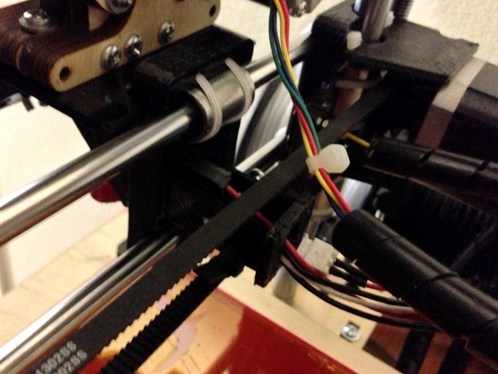
Secure the linear bearings to the extruder mount using four zip ties. Next mount the extruder and the 40mm fan into place. Feed the wires through the hole to the back of the mount.

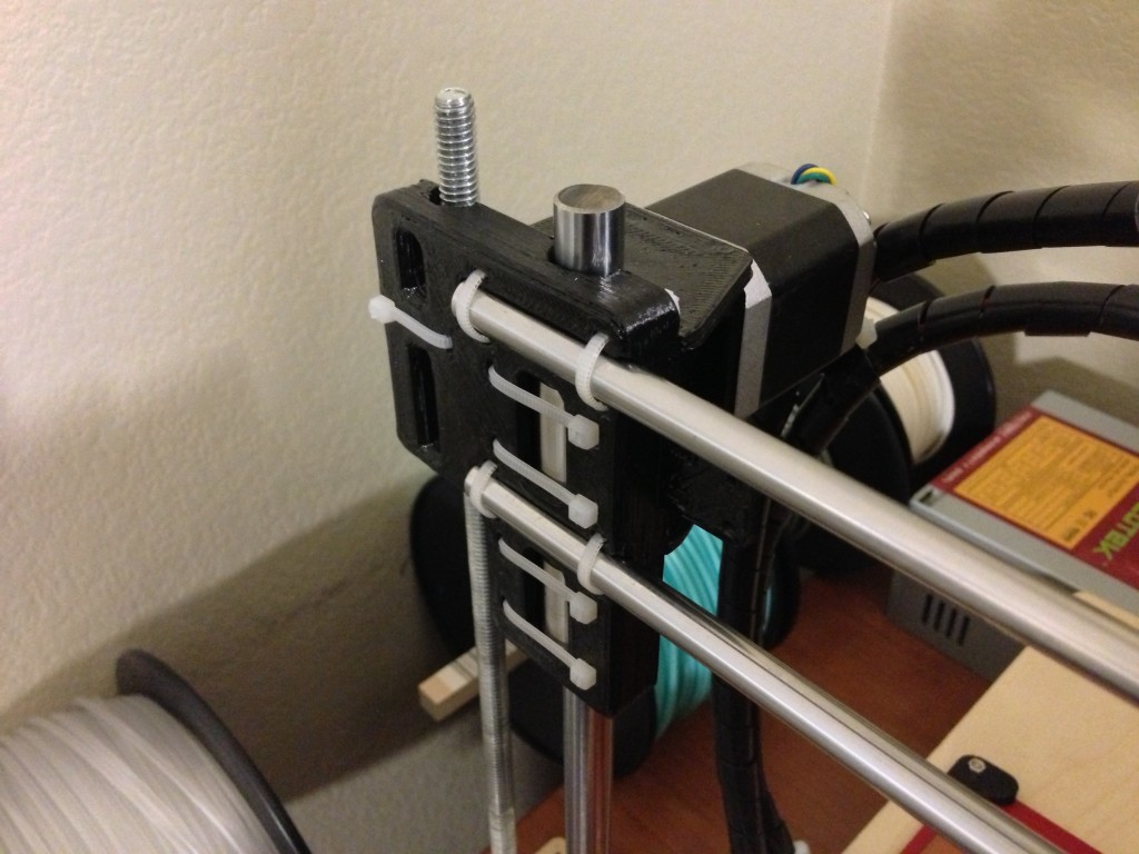
Slide the left bracket onto the rods and bolt the x-axis stepper motor with pulley to the motor mount. Align the motor mount to the back of the bracket and pull through four zip ties around the x-axis smooth rods. It is not necessary to glue the motor mount to the back of the left bracket.
Complete the installation by sliding the extruder mount onto the x-axis smooth rods and securing the right bracket to the rods.
Secure the belt to the rear of the exruder mount. Note that the belt must be fastened to the bottom side of the loop. This requires that the travel of the x-axis stepper motor be reversed. To do so, locate the connection for the x-axis stepper motor to the printrboard. Remove any two wires from the connector and replace them in reverse order.